The SPARK MAX can accept data from encoders through both the Encoder Port and the Data Port on the top of the motor controller. Encoders have a different method of connecting to the SPARK MAX that depends on what motor you are using and what type of encoder it is. When preparing your encoders, be sure to set up your SPARK MAX correctly for the type of devices you are using.
Incremental vs Absolute Encoders
Incremental encoders measure a change in position as a mechanism rotates while absolute encoders will report an exact position at any time, including at startup. A common analogy to help with knowing the difference is that incremental encoders are like a stopwatch that measures a change in time and absolute encoders are like a clock where you can know exactly what time it is.
With SPARK MAX Firmware Versions 1.6.0 and newer, absolute encoders are compatible with the SPARK MAX Data Port.
How to Connect an Encoder
To connect an encoder to your SPARK MAX, start by identifying what type of encoder you are using. Below is a flowchart to help generally identify the method you should use.
Running a brushless motor, like the NEO and NEO 550, without the integrated encoder plugged into the SPARK MAX's Encoder Port can damage your motor.
Absolute Encoders
Absolute encoders will work with the default pinout of the SPARK MAX Data Port if the latest firmware has been installed. When using an absolute or duty cycle encoder it is recommended to use one of the following methods to connect your encoder to the SPARK MAX.
: Connect with
Other Absolute Encoder: Connect with
Use the Data Port Pinout to match the signals from your encoder
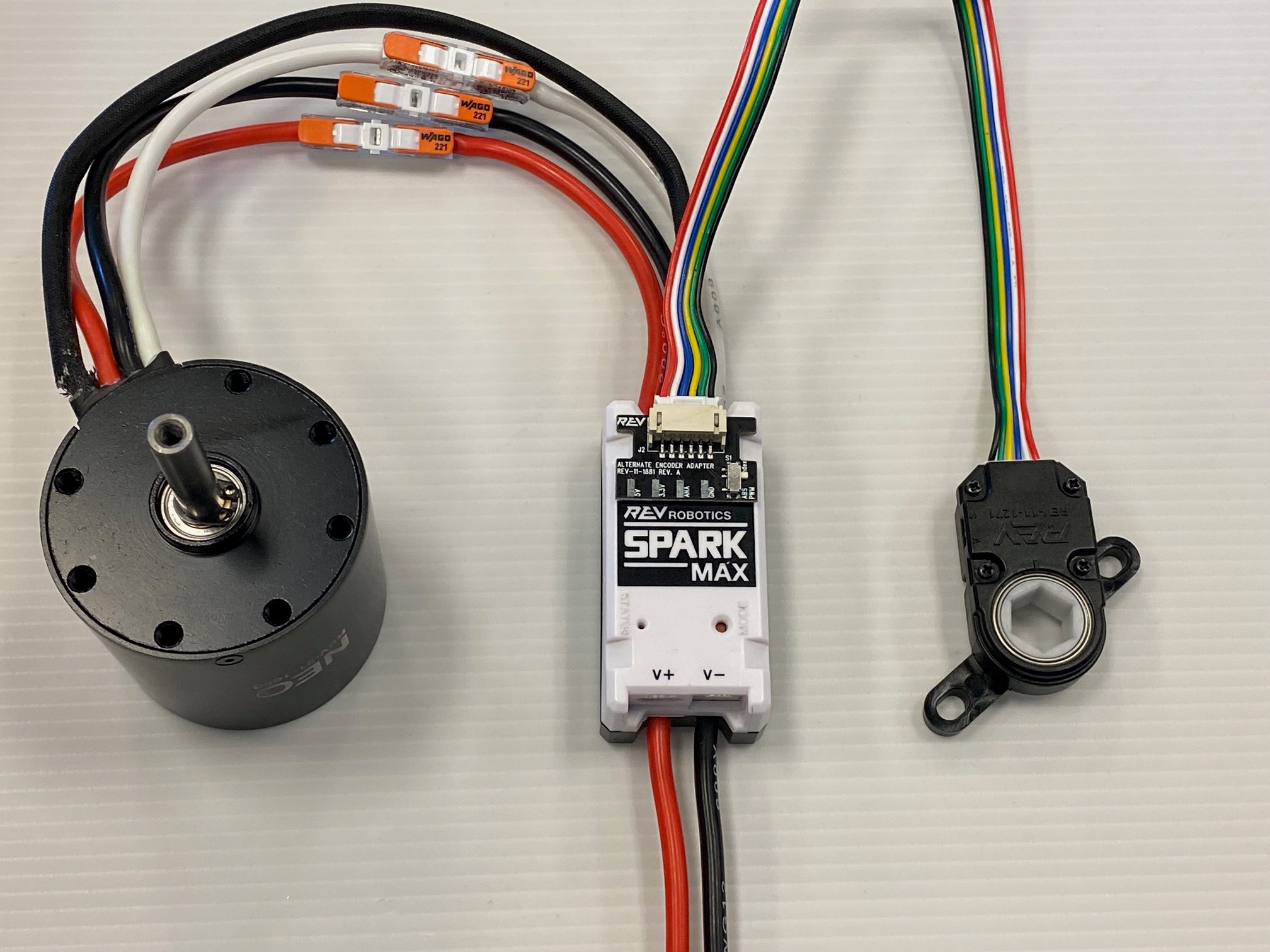
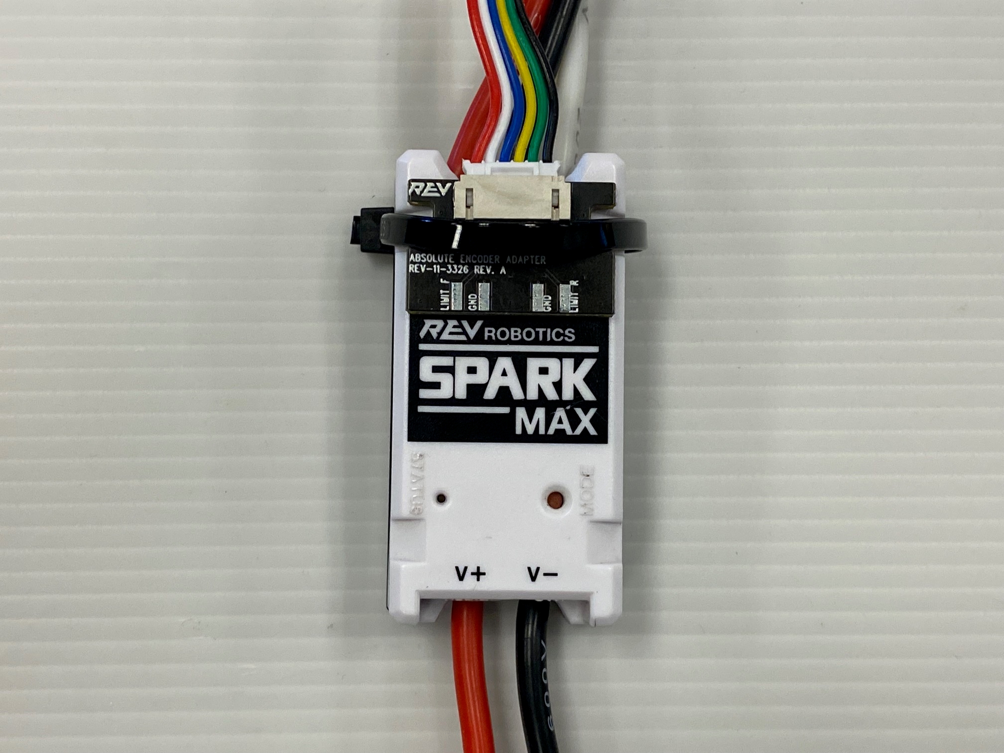
Easily connect a Through Bore Encoder to your SPARK MAX with an Absolute Encoder Adapter and a 6-Pin JST PH Cable.
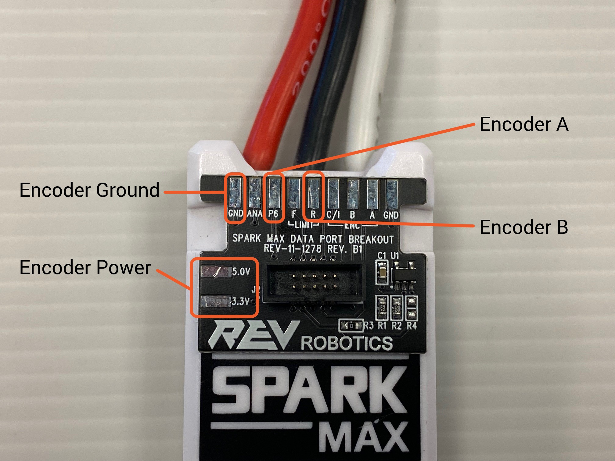
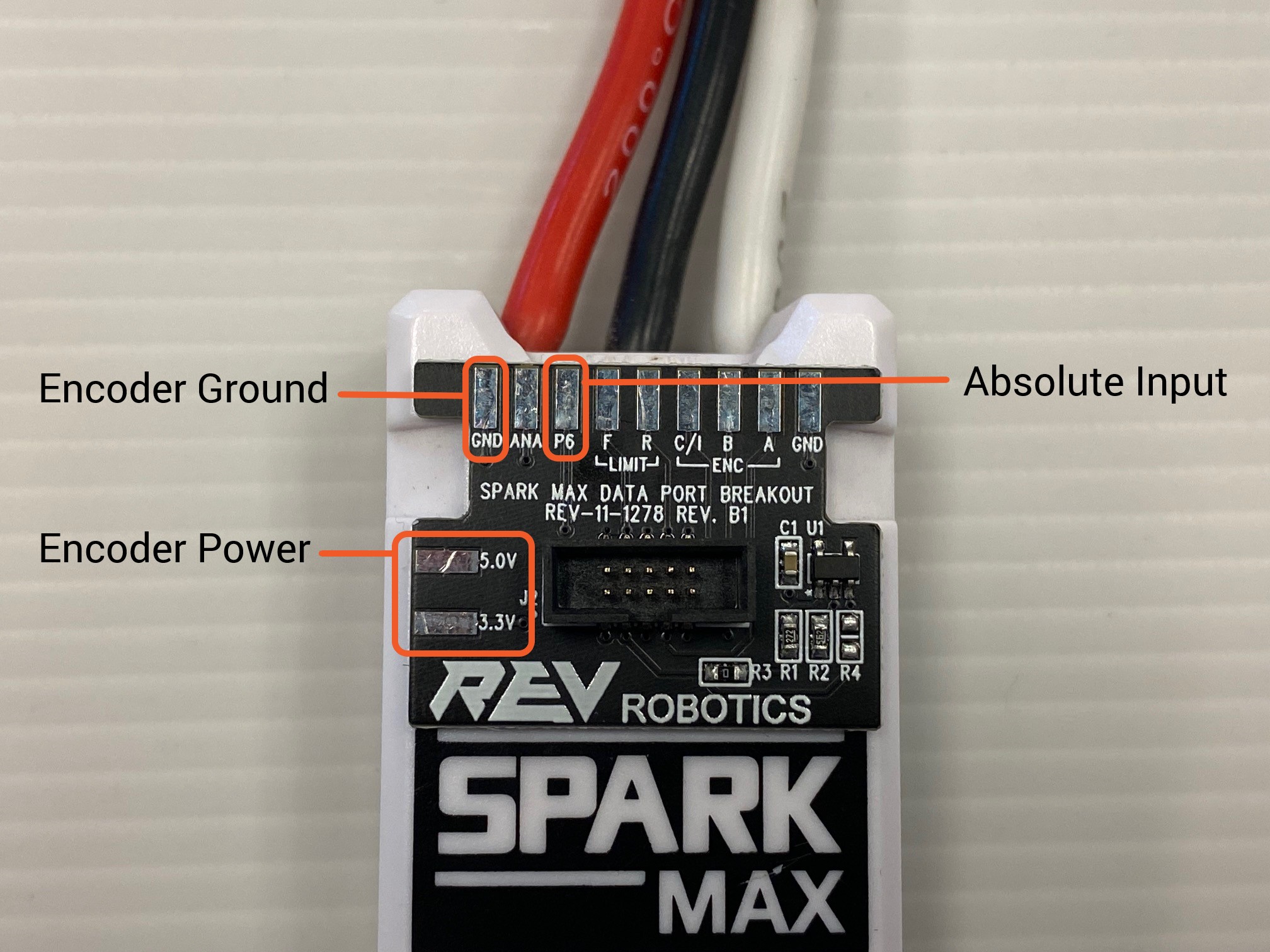
For encoders that need a custom wiring harness, you can use the following solder pads on a SPARK MAX Data Port Breakout Board with any generic absolute encoder.
If you are using an Incremental Encoder with a brushed motor you can plug your encoder into the SPARK MAX's front Encoder Port directly. If you are driving a NEO or NEO 550 brushless motor with your SPARK MAX, you will need to configure Alternate Encoder Mode to accommodate the additional encoder input from the Data Port. When using an incremental or quadrature encoder it is recommended to use one of the following methods to connect your encoder to the SPARK MAX.
or Internal Encoder: MUST be connected to the SPARK MAX Encoder Port
With brushless motor: Connect with . You will need to configure Alternate Encoder Mode.
Easily connect a Through Bore Encoder to your SPARK MAX with an Alternate Encoder Adapter and a 6-Pin JST PH Cable. When using the Alternate Encoder Adapter make sure the switch is set to "index".
A Through Bore Encoder, or any incremental encoder with the same pinout, can be plugged in directly to the SPARK MAX's Encoder Port.
For encoders that need a custom wiring harness, you can use the following solder pads on a SPARK MAX Data Port Breakout Board with any generic incremental encoder.
Receiving both Incremental and Absolute encoder feedback from a single encoder through the SPARK MAX directly is not currently supported. To do this you will need to wire the encoder directly to your roboRIO or robot controller.
Currently, Limit Switch inputs are only supported when using an absolute encoder or an incremental encoder run through the SPARK MAX's Encoder port. Please note, the limit switch inputs cannot be used at the same time as an Alternate Encoder Mode. The limit switch pins are repurposed for the alternate encoder and are thus disabled.
With brushed motor: Connect to the Encoder Port
Other Incremental Encoder
With a brushless motor: Connect the encoder with SPARK MAX Data Port Breakout Board (REV-11-1278). Use the Alternate Encoder Mode Data Port Pinout to match the signals from your encoder. You will need to configure Alternate Encoder Mode.
The SPARK MAX does not need to be configured to a specific mode to accept input from an absolute encoder as long as the encoder is connected to the SPARK MAX Data Port.
Absolute Encoder Specifications
Parameter
Specification
Encoder Output Voltage Level
5.0V
Connecting an absolute encoder that is not a Through Bore Encoder will likely require a custom wiring harness or to connect the necessary encoder power, ground, and signals to the SPARK MAX Data Port. When using an Absolute Encoder use the following pinout information for the Data Port:
+5V
3
Analog
Analog Input
4
Digital
Forward Limit Switch Input
5
Digital
Encoder B
6
Digital
Absolute/PWM Input
7
Digital
Encoder A
8
Digital
Reverse Limit Switch Input
9
Digital
Encoder C / Index
10
Ground
Ground
Encoder Type Supported
Duty Cycle or PWM
Connector Pin
Pin Type
Pin Function
1
Power
+3.3V
2
Absolute encoder input is supported by SPARK MAX Firmware Version 1.6.0 and newer,
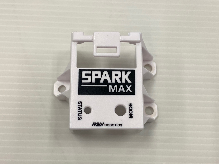
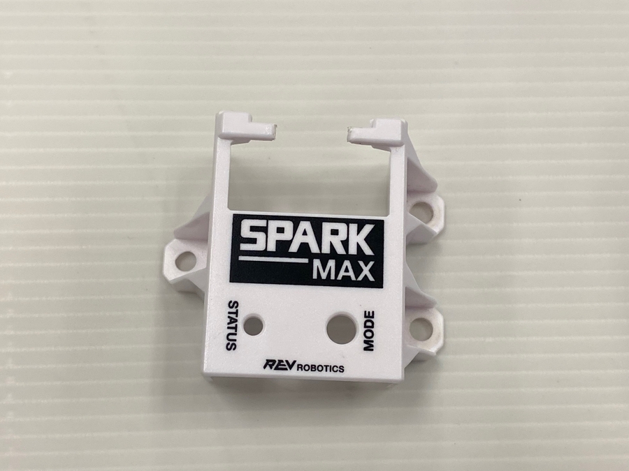
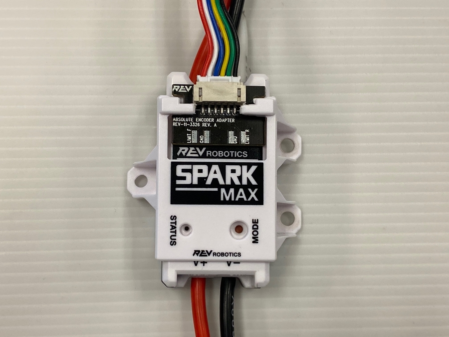
The Encoder Adapters and SPARK MAX Data Port Breakout Boards can be secured to a SPARK MAX in two ways.
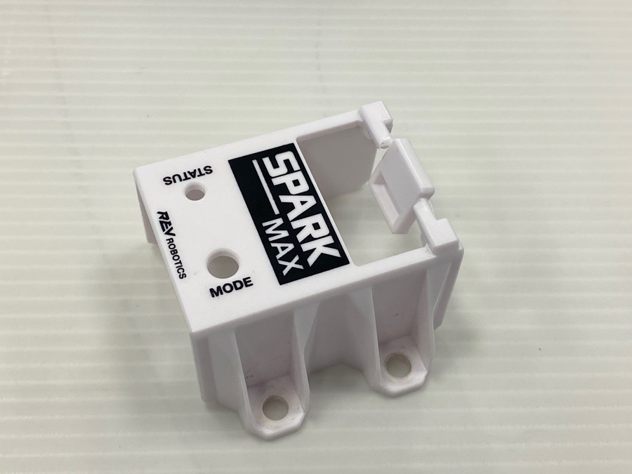
SPARK MAX Mounting Bracket ()
Description
Image
1) To use a SPARK MAX Mounting Bracket to secure your Encoder Adapter or Breakout Board you will need to remove the middle tab of plastic
A zip-tie can be secured around the SPARK MAX's zip-tie notches and over the board to securely attach it to the motor controller as well.
2) Cut this piece of plastic with a pair of snips, or remove it by twisting the plastic until it breaks
3) Once the middle piece of plastic has been removed, remove any sharp edges with a file or some sandpaper
4) The SPARK MAX Mounting Bracket will fit over the board as shown in this image. Attach the mounting bracket to your surface as you normally would after this step
The SPARK MAX can be configured to run in Alternate Encoder Mode, which reconfigures the Data Port on the top of the controller to accept an alternative quadrature encoder, separate from the default encoder inputs shared between the front Encoder Port and the default quadrature encoder Data Port pins. Analog input is not affected by Alternate Encoder Mode.
This feature is designed for use in low-RPM mechanisms such as drivetrains, arms, and other manipulators. For high RPM applications, it is recommended to use the built-in motor sensor for brushless motors or the default encoder inputs for brushed motors.
Alternate Encoder Specifications
Parameter
Specification
Encoder Output Voltage Level
3.3V or 5.0V
When configured for Alternate Encoder Mode, a quadrature encoder connected to the reconfigured Data Port pins can be used as a feedback device by the SPARK MAX. Please note, the limit switch inputs cannot be used at the same time as an alternate encoder. The limit switch pins are repurposed for the alternate encoder and are thus disabled. Please see for for more information.
Connecting an alternate encoder will likely require a custom wiring harness to connect the necessary encoder power, ground, and signals to the reconfigured Data Port. When configured in Alternate Encoder Mode, the Data Port has the following pinout:
Use an Alternate Encoder Adapter () to connect a directly to the SPARK MAX Data Port. This adapter has a JST PH 6-pin connector that is compatible with the Through Bore Encoder's pinout and a selection switch to change the signal that is connect to pin 4 of the data port.
Another option is the . This board can be used to wire an alternate encoder to the Data Port. The following table describes which pads on the breakout should be used for which signals coming from the alternate encoder.
Below you will find the steps required to set up and use the Alternate Encoder Mode on the SPARK MAX, starting with configuration through either the REV Hardware Client or the SPARK MAX APIs.
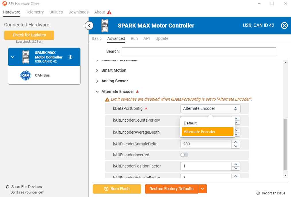
Using the REV Hardware Client, select your SPARK MAX, then navigate to the Advanced Tab and scroll to the Alternate Encoder parameter section. Enable the alternate encoder by setting the kDataPortConfig parameter to 'Alternate Encoder' via the drop down menu. You can also set the other Alternate Encoder parameters at this time.
If using the SPARK MAX APIs, the Alternate Encoder is automatically configured when the Alternate Encoder object is instantiated. An Alternate Encoder is created the same as a CANEncoder, either by directly using the constructor or calling GetAlternateEncoder() on a previously constructed CANSparkMax.
Currently, quadrature is the only available type of configuration for an alternate encoder. This is differentiated from the other types of encoder configurations available for an encoder connected through the front facing Encoder Port on the SPARK MAX.
Since the alternate encoder inputs and the default digital inputs are shared on the Data Port, the user cannot use both the alternate encoder and a digital inputs in code. Therefore, a std::invalid_argument (C++), IllegalArgumentException (Java), or an Error on the Error Out terminal (LabVIEW) will be thrown if a user tries to construct both types objects in code simultaneously.
The alternate encoder can be used with the different closed-loop control modes available on the SPARK MAX. The feedback device used by a CANPIDController must be set to use the alternate encoder through SetFeedbackDevice().
Unlike the built-in sensor on the NEO Brushless motors, the 'phase' of the alternate encoder is unknown to the SPARK MAX. Before enabling any closed-loop control, it is critical that the phase is configured correctly. To verify:
Configure and connect the sensor as a quadrature alternate encoder, but do not run a closed-loop mode.
Plot the output signal of the motor using GetAppliedOutput() and the output of the encoder using altEncoder.GetVelocity(). Confirm that the sensor is behaving as expected. This can be done on the SmartDashboard:
frc::SmartDashboard::PutNumber("Alt Encoder Velocity", m_alternateEncoder.GetVelocity());
frc::SmartDashboard::PutNumber("Applied Output", m_motor.GetAppliedOutput());
2400
Greyhill 63R256
1024
9600
+5V
3
Analog
Analog Input
4
Digital
Alternate Encoder Index†
5
Digital
Encoder B
6
Digital
Alternate Encoder A
7
Digital
Encoder A
8
Digital
Alternate Encoder B
9
Digital
Encoder C / Index
10
Ground
Ground
B
3.3V or 5.0V
Encoder Power
GND
Encoder Ground
Verify that the sign of the sensor is correct relative to the motor direction when driving it forward and backward. If it is not, the sensor must be inverted by calling altEncoder.SetInverted(true).
The Alternate Encoder Index pin is reserved but not currently supported
Breakout Board Pad Label
Alternate Encoder Function
Limit - F
Index†
P6 (P5 in older batches)
A
†
The Alternate Encoder Index pin is reserved but not currently supported
static constexpr int kCanId = 1;
static constexpr auto kMotorType = rev::CANSparkMax::MotorType::kBrushless;
static constexpr auto kAltEncType = rev::CANEncoder::AlternateEncoderType::kQuadrature;
static constexpr int kCPR = 8192;

// initialize SPARK MAX with CAN ID
rev::CANSparkMax m_motor{kCanID, kMotorType};

/**
* An alternate encoder object is constructed using the GetAlternateEncoder()
* method on an existing CANSparkMax object. If using a REV Through Bore
* Encoder, the type should be set to quadrature and the counts per
* revolution set to 8192
*/
rev::CANEncoder m_alternateEncoder = m_motor.GetAlternateEncoder(kAltEncType, kCPR);
/**
* By default, the PID controller will use the Hall sensor from a NEO or NEO 550 for
* its feedback device. Instead, we can set the feedback device to the alternate
* encoder object
*/
m_pidController.SetFeedbackDevice(m_alternateEncoder);
Before connecting a sensor with 5V output, the SPARK MAX must first be updated to firmware version 1.5.0 or later, or damage may occur. This can be done through the REV Hardware Client.