In the fall of 2018, the NEO Brushless Motor and SPARK MAX Motor Controller became the first brushless motor and compatible ESC (Electronic Speed Controller) designed to meet the unique demands of the FRC community. Since then, REV Robotics has been working to continue the Brushless Revolution by releasing products and software features based on our customer's most popular feedback.
The Next Generation of Motors and Controllers
NEO Vortex Brushless Motor
The NEO Vortex Brushless Motor is a high-power, high-performance, and high-resolution sensored brushless motor from REV Robotics. It features a dockable controller interface that can be mounted directly to a SPARK Flex Motor Controller or a NEO Vortex Solo Adapter allowing control from any brushless motor controller, like the SPARK MAX. Its through-bore rotor is the heart of its unique interchangeable shaft system, facilitating easy integration with various robot mechanisms.
SPARK Flex Motor Controller
The SPARK Flex Motor Controller is a new smart motor controller from REV Robotics. Its dockable form factor allows direct mounting onto a NEO Vortex to simplify wiring and maintain flexibility. Improving upon the foundation of the SPARK MAX, new features of the SPARK Flex Motor Controller include 3-phase current sensing, reverse polarity protection, and an expanded data port with additional interfaces. When docked to an adapter, the SPARK Flex can control any existing NEO or compatible brushless/brushed DC motor.
Incredible Power Density and Integrated USB Control
SPARK MAX Motor Controller
The SPARK MAX Motor Controller is your first step for getting advanced brushed and brushless DC motor control in a small, easy-to-use package. SPARK MAX is a true all-in-one controller that will push the envelope for FRC teams. Test prototypes and tune parameters without needing the full control system, only using a computer running the REV Hardware Client and a USB C Cable!
NEO V1.1 Brushless Motor
The NEO V1.1 Brushless Motor offers an incredible power density due to its compact size and reduced weight. As it is designed to have similar performance characteristics and matching mounting features, NEO V1.1 can be a drop-in replacement for CIM-style motors. This motor is perfect for your FRC Robot, Industrial platform or Warehouse robot, Electric skateboards, and more! The NEO V1.1 has been optimized to work with the SPARK MAX Motor Controller to deliver best-in-class performance and feedback.
NEO 550 Brushless Motor
The NEO 550 Brushless Motor is the smallest member of the NEO family of brushless motors. Its output power and small size are designed to make NEO 550 the perfect motor for intakes and other non-drivetrain robot mechanisms. Mounting holes and pilot match a standard 550 series motor, making it natively compatible with many existing off-the-shelf gearboxes.
If there is a question that is not answered by this space, send our support team an email; support@revrobotics.com. We are always happy to help point you in the right direction!
Brushless DC Motor Basics
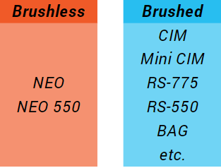
DC Motors consist of two major parts, the part that rotates, or the “rotor”, and the part that is stationary, or the “stator”. A DC motor uses these parts to convert electrical energy into rotational mechanical energy using electricity and permanent magnets. Two types of DC motors are used in FIRST Robotics Competition: Brushed DC Motors and Brushless DC motors. Both types are useful in various robot applications, and both have their trade-offs.
Brushless vs. Brushed Motor Basics
Operating a brushed DC motor is simple; provide DC electrical power and the motor spins. In a brushed motor, the rotor consists of electrical winding wires and the stator consists of permanent magnets. Since the electrical part is spinning, there needs to be a way to connect the external power wires to the spinning rotor. This is accomplished through conductive “brushes” that make contact with the stator, automatically sequencing the power to make the rotor spin. Brushes make it easy on us, but they produce extra friction which reduces the efficiency of the motor.
Brushless DC motors don’t have brushes. They still have both electrical winding wires and permanent magnets, but the locations are flipped. The stator now consists of the electrical parts, and the spinning rotor consists of the magnets. This means there is no more brush friction within the motor, making a brushless motor more power-efficient. However, you can’t just give it DC power and expect it to spin. Without the brushes doing the sequencing for us, you must use a specialized motor controller that is designed for brushless motors to properly sequence the power and get the rotor spinning.
The REV NEO Brushless Motor runs an 8mm keyed output shaft which allows for an easy transition from CIM-style brushed motors into brushless.
Swap a set of NEO Brushless Motors into your drivetrain or use one in an elevator to save weight and maintain peak performance. When paired with the SPARK MAX, you can use the integrated hall-effect sensors to calculate incremental position or speed from the NEO.
Key Terms
Stall Torque is measured when the motors RPM is zero and the motor is drawing its full Stall Current. This value is the maximum torque the motor is ever capable of outputting. Keep in mind the motor is not capable of outputting this torque for an indefinite period of time. Waste energy will be released into the motor as heat. When the motor is producing more waste heat than the motor body is capable of dissipating the motor will eventually overheat and fail.
Stall Current is the maximum amount of current the motor will draw. The stall current is measured at the point when the motor has torque that the RPM goes down to zero. This is also the point at which the most waste heat will be dissipated into the motor body.
Free Speed is the angular velocity that a motor will spin at when powered at the Operating Voltage with zero load on the motor’s output shaft. This RPM is the fastest angular velocity the motor will ever spin at. Once the motor is under load its angular velocity will decrease.
Operating Voltage is the expected voltage that the motor will experience during operation. If a robot is built using a 12 volt battery the Operating Voltage of the motor will be 12 volts. When controlling the RPM of the motor the DC speed controller will modulate the effective voltage seen by the motor. The lower the voltage seen by the motor the slower it will spin. DC motors have a maximum rated voltage if this voltage is exceeded the motor will fail prematurely.
The key metrics defined above are interrelated. Take some time to familiarize yourself with the definitions and how they connect together.
General Application Information
In order to ensure that an electric motor lasts as long as possible a few rules of thumb should be kept in mind:
Smooth loading - large torque spikes or sudden changes in direction can cause excess wear and premature failure of gearbox components. This is only an issue when the torque spike exceeds the rated stall torque of the motor. When shock loading is necessary, it is best to utilize mechanical braking or a hard stop that absorbs the impact instead of the motor.
Overheating - when a motor is loaded at near its maximum operating torque it will produce more waste heat than when operating at a lower operating torque. If this heat this allowed to build up the motor can wear out prematurely or fail spontaneously.
Poorly supported output shaft, most motor output shafts are not designed to take large thrust forces or forces normal to the shaft. Bearings need to be used to support the axle when loads in these directions are expected.
Installing a Shaft
Shaft Installation Materials
Installing a Vortex Shaft is simple and requires the following materials and tools:
NEO Vortex (docked or undocked)
Desired Vortex Shaft
#10-32 Shaft End Screw
5/32 in Hex Key
Shaft Installation Procedure
Follow these steps to ensure a secure shaft installation:
Insert the shank of the desired shaft into the Vortex Spindle from the front mounting face of the motor.
While inserting, you may need to rotate the shaft or rotor slightly to align the hexagonal portion of the shank with the hexagonal bore of the spindle.
Once the shaft is fully inserted, install the Shaft End Screw through the back side of the spindle and thread into the shank.
Tighten the Shaft End Screw with the 5/32 in hex key to draw the taper into a locked and centered position. If you have a torque wrench, the ideal torque is 25 ±5 in-lb (2.8 ±0.6 Nm).
Visually check for concentricity by rotating the motor rotor. If the shaft is not concentric, remove it, rotate its orientation, and reseat in the spindle.
Shaft Removal Procedure
Remove the Shaft End Screw with the 5/32 in hex key.
Remove the Vortex Shaft from the motor.
While the Vortex Shaft taper is designed to self release, it may still need a gentle tap to help it along. Be sure to tap the shaft itself and not the rotor. You can partially back out the Shaft End Screw and tap it to push the shaft out.
Flex Dock
Flex Dock Overview
The Flex Dock transforms the SPARK Flex (REV-11-2159) into a standalone motor controller, supporting REV brushless motors and virtually any 12V brushed DC motor by providing standard phase wire outputs. The 6-pin JST PH encoder port is compatible with NEO/NEO550 hall sensors in brushless mode and standard quadrature encoders in brushed mode.
Flex Dock
The dock securely mounts to a SPARK Flex using the same docking hardware as if you were mounting to a NEO Vortex. It features five #10-32 threaded mounting holes on a 0.5-inch grid, enabling versatile mounting on either face of the combined stack.
Additionally, the Flex Dock offers added protection against common faults caused by damaged motors or wiring. Compact and lightweight, it empowers you to adapt a SPARK Flex to meet your specific motor control requirements.
Flex Dock Features
Docks to Spark Flex with standard M3 docking hardware (not included)
Five #10-32 threaded holes on 0.5in grid with max depth of 0.25in for mounting
Flex Dock Specifications
Body:
Material: Aluminum
Finish: Black Anodized
Length (Docked with SPARK Flex): 35mm (1.378in)
Motor Phase Wires:
Length: 150mm (5.91in)
12AWG
Encoder Port:
6-pin JST PH
Primary encoder input for:
When in Brushless Mode: NEO or NEO550's built in hall sensor encoder.
When in Brushed Mode: Standard quadrature encoder with index (ABI).
Note: Does not support absolute (duty cycle) encoders. Use the SPARK Flex Data Port for absolute encoders.
Electrical Fault Protection
Protects the SPARK Flex from typical faults caused by damaged motors or motor wires.
Weight 64g (0.141lb)
Control Connections
The SPARK Flex can be controlled by three different interfaces: servo-style PWM, Controller Area Network (CAN), and USB. The following sections describe the physical connections to these interfaces. For details on the operation and protocols of the PWM, CAN, or USB interfaces, please see Control Interfaces.
SPARK Flex Control Connections
CAN/PWM Connections
CAN and PWM control connections share a set of four integrated 26 AWG twisted wires extending 45 cm from the case of the motor controller. Each wire is color coded according to its function:
Wire Color
CAN Function
PWM Function
Yellow
CAN High (CANH)
Signal
Green
CAN Low (CANL)
Ground
The wires are terminated with two 1 x 3, 0.1 in pitch, rectangular connectors, both excluding the center pin. One connector is pinned and the other socketed to facilitate daisy-chaining between multiple CAN devices on the bus when using the CAN interface.
Each matching wire pair is physically connected to its functional counterpart within the device. Even if the SPARK Flex loses power, the CAN bus remains unbroken, leaving downstream devices unaffected.
Pay close attention when daisy-chaining devices, and make sure that the colors match from connector-to-connecter along the entire CAN bus. Mismatched connections can cause difficult-to-diagnose communications issues along the entire bus.
When using the PWM interface, only one of the two connectors should be used. In most systems this will be the socketed connector. Therefore, it is best practice to secure the unused wires and protect the exposed pins by covering them with electrical tape.
When daisy-chaining or extending the connections, use the included PWM Cable Clips (REV-11-1229) to secure the two mating connectors together to prevent unintended disconnections.
USB-C Port
The USB-C Port is located above the CAN/PWM wires of the SPARK Flex. It supports USB 2.0 and can provide 5 V power for the SPARK Flex's internal microcontroller.
While you can configure the SPARK Flex under USB-only power, you will not be able to spin a motor unless main power is also connected.
More information about what can be configured and operated through the USB port can be found in the USB Interface section.
Mounting Holes
The mounting face of the SPARK Flex features six #10-32 threaded mounting holes on a 2 in bolt circle. Each hole has an absolute maximum depth of 0.25 in.
SPARK Flex Mounting Hole Pattern
DO NOT exceed the maximum mounting screw depth of 0.25 in when mounting the SPARK Flex. Doing so will result in permanent damage to the SPARK Flex and will void the warranty.
Depth gauges are laser-etched into each side of the SPARK Flex body to make it easy to check that the chosen screw length will not violate the maximum depth.
SPARK Flex Mounting Screw Depth Gauge
Simply check the screw length against the intended stack-up of structure and motor controller, and verify that it does not violate the maximum depth.
Checking Screw Length with SPARK Flex Mounting Screw Depth Gauge
Control Interfaces
The SPARK Flex can be controlled by three different interfaces: servo-style PWM, Controller Area Network (CAN), and USB. The following sections describe the operation and protocols of these interfaces. For more details on the physical connections, see Control Connections.
PWM Interface
The SPARK Flex can accept a standard servo-style PWM signal as a control for the output duty cycle. Even though the PWM port is shared with the CAN port, SPARK Flex will automatically detect the incoming signal type and respond accordingly. For details on how to connect a PWM cable to the SPARK Flex, see CAN/PWM Connections.
The SPARK Flex responds to a factory default pulse range of 1000 µs to 2000 µs. These pulses correspond to full-reverse and full-forward rotation, respectively, with 1500 µs (±5% default input deadband) as the neutral position, i.e. no rotation. The input deadband is configurable with the REV Hardware Client or the CAN interface. The table below describes how the default pulse range maps to the output behavior.
PWM Pulse Mapping
If a valid signal isn't received within a 60 ms window, the SPARK Flex will disable the motor output and either brake or coast the motor depending on the configured Idle Mode. For details on the Idle Mode, see Idle Mode - Brake/Coast Mode.
CAN Interface
The SPARK Flex can be connected to a robot CAN network. CAN is a bi-directional communications bus that enables advanced features within the SPARK Flex.
SPARK Flex must be connected to a CAN network that has the appropriate termination resistors at both endpoints. Please see the FIRST Robotics Competition Robot Rules for the CAN bus wiring requirements.
Even though the CAN port is shared with the PWM port, SPARK Flex will automatically detect the incoming signal type and respond accordingly.
Each device on the CAN bus must be assigned a unique CAN ID number. Out of the box, SPARK Flex is assigned a device ID of 0. This ID is considered "unconfigured" and must be assigned to a unique number from 1 to 62. CAN IDs can be changed by connecting the SPARK Flex to a Windows computer and using the REV Hardware Client.
Additional information about the CAN accessible features and how to access them can be found in the SPARK Flex API Information section.
USB Interface
The SPARK Flex can be configured and controlled through a USB connection to a computer running the REV Hardware Client.
More information coming soon!
Mode Button
The mode button can be used to activate basic operating modes within the SPARK Flex. For information on those modes, please see the Operating Modes section.
Pressing the SPARK Flex Mode Button
The Mode Button is specifically designed to be difficult to press inadvertently. Therefore, please follow the steps below to press the mode button successfully.
Using a small and blunt tool, like a straightened paper clip, gently press the Mode Button. You should feel and hear a soft click. If you are in a noisy environment, you may only be able to feel the click through the tool.
DO NOT use a sharp tool to press the Mode Button.
Safety pins, thumbtacks, pinbacks buttons, and other sharp tools will cause damage to the Mode Button's material.
If you do not feel the click, ensure the tool is aligned with the button.
DO NOTpress with excessive force.
You should feel the click of the button with relatively gentle pressure. Pressing with excessive force can permanently damage the button.
Some early batches of SPARK Flex Motor Controllers have variances in the alignment of the Mode Button and the case hole. Misaligned buttons can still be pressed and the alignment does not affect the functionality of the SPARK Flex Motor Controller as a whole.
If your button is misaligned, please pay close attention and avoid the gap between the button and the printed circuit board (PCB):
Tips for Pressing a Misaligned Mode Button
Again, DO NOT use a sharp tool to press a misaligned Mode Button. It can easily be inserted into the indicated gap above, and permanently damage the button.
Generally, a sharp tool should never be used to press the Mode Button.
Please reach out to us at support@revrobotics.com if you are still having difficulty pressing your Mode Button after following this guide.
SPARK Flex Getting Started
SPARK Flex Anatomy
Side View
Outside
Inside
The SPARK Flex is a motor controller with many features allowing it to control a host of brushless and brushed motor controllers. Out of the box, the Flex can be docked directly with a NEO Vortex Brushless Motor and drive it with the Flex's PWM interface. This Getting Started guide will assume that you are driving NEO Vortex and includes steps to get the motor spinning using the REV Hardware Client as well as information on how to configure your SPARK Flex.
Driving other motors requires the SPARK Flex Dock (coming soon) and will be covered in its own separate guides.
Before You Start
Before following this guide, the REV Hardware Client should be installed before continuing. It is the best way to verify that the device up to date and configured correctly. Configuration through the Hardware Client is required before using the CAN interface.
Basic Configurations
SPARK Flex has many operating modes that can be configured through its CAN and USB interfaces.
Coming soon!
Basic Configurations
SPARK MAX has many operating modes that can be configured through its CAN and USB interfaces. Additionally, the following basic operating modes can be configured with the MODE button located on the top of the SPARK MAX:
Mode configuration must be done with power applied to the SPARK MAX.
Configuring the idle behavior and motor type using the mode button is a quick way to set up a SPARK MAX without using a computer. This is most useful when you are controlling the SPARK MAX through its PWM interface or when testing the affect of Braking or Coasting on a mechanism.
Idle Behavior
Whenever the SPARK MAX receives a neutral signal (no motor movement) or no signal at all (robot disabled), it can either brake the motor or let it coast. When in Brake Mode, MAX will short the motor wires to each other, electrically braking the motor. This slows the motor down very quickly if it was spinning and makes it harder, but not impossible to back-drive the motor when it is stopped.
With power turned on, press and release the MODE button to switch between Brake and Coast Mode.
This is legacy documentation for our discontinued SPARK MAX Client Software. If you are interested in running a SPARK MAX via a computer, please see our newer documentation: Getting Started with the REV Hardware Client.
When updating the firmware on the SPARK MAX, it is possible for the process to be interrupted or for the firmware to be corrupted by a bad download. In this state, the Status LED will be dark and the SPARK MAX will fail to operate. SPARK MAX has a built-in recovery mode that can force it to accept new firmware even if the controller seems to be bricked. The following procedure requires a small tool, like a straightened paper clip, to press the Mode Button, a USB C cable, and a computer with the SPARK MAX Client Application installed:
With the SPARK MAX powered off completely, press and hold the Mode Button.
While still holding the Mode Button, connect the SPARK MAX to the computer using the USB cable. The Status LED will not illuminate, this is expected.
Wait a few seconds for the computer to recognize the connected device, then release the Mode Button.
Open the SPARK MAX Client Application. The SPARK MAX will remain dark and it will not connect to the Client, this is expected.
Navigate to the Network tab and click the Rescan arrows at the top of the window.
The SPARK MAX will be listed under Devices in Recovery Mode. Click the checkbox next to the device.
Click the Load Firmware button.
Select the latest firmware file and click Open.
The firmware should load successfully and the SPARK MAX will now connect to the Client.
Docking a SPARK Flex
When docked with a SPARK Flex the NEO Vortex's phase and sensor connections are kept securely together. This eliminates intermediate wiring that can fail if not secured properly.
Docking Materials
Docking the NEO Vortex with the SPARK Flex is simple and only requires the following materials and tools:
NEO Vortex Brushless Motor
SPARK Flex Motor Controller
Docking Hardware
4 - M3 x 25 mm Socket Head Screws (included with SPARK Flex)
2.5 mm Hex Key
Docking Procedure
Follow these steps to ensure a secure and proper docking:
Ensure that power is disconnected from the SPARK Flex.
Align the motor phase bullets between the NEO Vortex and SPARK Flex.
Allowing the bullets to guide the two together, press the NEO Vortex and SPARK Flex together until their bodies meet. There may be a small gap between the motor and the controller opposite the bullets. This is normal.
Insert the included docking screws into the counterbored Docking Screw Clearance Holes on the SPARK Flex.
Using the 2.5 mm Hex Key, tighten the four screws evenly in a crisscross pattern until the screws are tight and secure. The screw heads should be sub-flush from the mounting face of she SPARK Flex. If you have a torque wrench, the ideal torque is 11.5 ±0.9 in-lb (1.3 ±0.1 Nm).
DO NOT run the motor without the docking screws installed. These screws ensure a robust and secure electrical connection, and doing so may cause damage to the system.
Undocking Procedure
Follow these steps to undock the NEO Vortex and SPARK Flex:
Ensure that power is disconnected from the SPARK Flex.
Completely remove the four docking screws from the assembly.
Gently pull the NEO Vortex and SPARK Flex apart until the bullets release. Try to maintain their relative orientation to each other while pulling them apart.
Vortex Shafts
NEO Vortex Shaft Features
Vortex shafts feature a 1/2 in hex section for transferring torque, and a locating taper section for effortless self-centering. When the shaft is secured with a #10-32 Shaft End Screw, the taper keeps your shaft perfectly centered as it's drawn in and locked into place within the NEO Vortex Spindle.
1) Place the NEO 550 upright in the arbor press. Make sure to hold the bottom of the motor flat against the press plate, supporting the bottom of the shaft.
2) Place the pinion on the shaft and press. Take care to not over-press on the NEO 550 shaft!
Locked Rotor Testing
When stalled, both brushed and brushless motors draw a lot of current and generate a large amount of heat. This heat can permanently damage a motor in a fraction of a second if not managed correctly. Locked-rotor stall data can be a useful tool when designing robot mechanisms that need to hold a mechanical load for a particular amount of time. It is useful to know the approximate time to failure depending on the applied load so that mechanisms can be successfully designed around these limitations.
Brushless motors, like the NEO family of Brushless Motors, offer higher efficiency and higher power density than brushed motors. However, they require a more complex control scheme to operate due to the fundamentally different motor technology. Sensors are built into each version of NEO Brushless Motors to enable proper operation with a SPARK MAX or SPARK Flex Motor Controller, and are required for proper operation.
Most Brushed DC motors used in FRC have locked-rotor stall data available showing Torque vs. Time at a particular constant applied voltage. This data shows how long a particular voltage can be applied before the motor fails. Because of differences in motor construction, especially winding resistance and torque constants, voltage data cannot be used alone to compare the survivability of different motors.
While applied voltage is straightforward and sometimes the only variable that you can control (e.g., with the original SPARK or Victor SPX), it isn’t as useful when you need to maintain a constant torque to hold a constant load. Over time, when a constant voltage is applied to a brushless motor, the motor's current and torque output will change as the motor's windings heat up.
SPARK Flex Overview
The SPARK Flex (REV-11-2159) is a new smart motor controller from REV Robotics. Its dockable form factor allows for direct mounting onto a NEO Vortex (REV-21-1652), simplifying wiring while maintaining flexibility. Improving upon the foundation of the SPARK MAX, new features include 3-phase current sensing, reverse polarity protection, and an expanded Data Port with additional interfaces. When docked to an adapter, the SPARK Flex can control any existing NEO or compatible brushless/brushed DC motor.
SPARK Flex Motor Controller
Feature Highlights:
Docking interface for motor phases and sensors
USB type C configuration and control
PWM and CAN communication
Fully integrated power and control wires
Enhanced data port with more power, latching connector, and additional serial interfaces
Advanced motor control modes include:
Velocity
Position
Current
New modes with future firmware updates
#10-32 threaded holes on a 2in bolt circle
Motor and motor controller's silhouette fits behind a standard 2in rectangular tube
The SPARK Flex Motor Controller is a fully featured smart motor controller designed to be robust and easy to use yet fully capable of advanced motion control. The following sections describe each feature in detail.
Precisely engineered clearance holes for docking screws provide stable and secure attachment of the SPARK Flex and NEO Vortex to your Mechanism
High-current Bullet Connectors facilitate quick and secure connections to the NEO Vortex's phases, ideal for high-performance and high-power applications
Robust Motor Interface Connector mates to the NEO Vortex's control systems to ensure efficient, secure, and reliable electrical connections and communication
SPARK Flex Docking Interface
The SPARK Flex features six #10-32 threaded mounting holes on a 2 in bolt circle
SPARK Flex Mounting Hole Pattern
Power and Motor Connections
SPARK Flex is designed to drive 12V brushed and brushless DC motors at current up to 60A continuously. It features a unique Docking Interface that ensures secure and reliable motor phase and sensor connections, reducing the chance of intermittent or poor connections affecting the commutation of the attached motor.
Power Input
Power input wires are labeled as + and - with red and black wires, respectively, and consist of two 12 AWG ultra-flexible silicone-coated wires extending 45 cm from the motor controller case.
SPARK Flex Power Wires
SPARK Flex is intended to operate in a 12 V DC robot system, however it is compatible with any DC power source between 4.5 V and 24 V.
Please note that the 5 V power output of the Data Port requires a 6 V minimum input voltage.
DO NOT exceed the maximum supply voltage of 30 V. Doing so will cause permanent damage to the SPARK Flex and will void the warranty.
When used in high power applications, it is recommended to use a power source that is capable of handling large surge currents, e.g. a 12V lead-acid battery. If the supply voltage drops below 4.5 V the SPARK Flex will brown out, which can result in unexpected behavior. It is also highly recommended to add a fuse or circuit breaker in between your SPARK Flex and its power source to prevent exceeding the maximum current rating.
DO NOT exceed the maximum current ratings:
60A for 3 minutes
100A for 2 seconds
Doing so will cause permanent damage to the SPARK Flex and will void the warranty.
Docking Interface
SPARK Flex is specifically designed to dock with the NEO Vortex Brushless Motor. Docking eliminates the extra connections between the motor and motor controller that are prone to fail due to assembly issues and rough environments.
When docked into a SPARK Flex Dock (coming soon), the motor controller can also drive virtually any 12 V brushed DC motor and the existing NEO & NEO 550 brushless motors.
SPARK Flex Docking Interface
Instruction on how to dock a SPARK Flex can be found within the documentation of the applicable device:
Be sure to fully install the Docking Screws when docking the SPARK Flex. These screws ensure a robust and secure electrical connection. Operating the SPARK Flex and its attached motor or dock without these screws can cause unintended behavior and damage to the system.
Always dock and undock the SPARK Flex with both main power and USB power disconnected.
Operating Modes
This mode is only compatible with the SPARK Flex Dock (coming soon). More information about this mode will be available once the dock is available.
When the SPARK Flex is receiving a neutral command the idle behavior of the motor can be handled in two different ways: Braking or Coasting.
When in Brake Mode, the SPARK Flex will effectively short all motor wires together. This quickly dissipates any electrical energy within the motor and brings it to a quick stop.
When in Coast Mode, the SPARK Flex will effectively disconnect all motor wires. This allows the motor to spin down at its own rate.
The Idle Mode can be configured using the Mode Button, CAN, and USB interfaces.
Wiring the SPARK Flex
Required Materials
12 V battery
120 A circuit breaker
Power Distribution Hub
SPARK Flex
NEO Vortex
Associated wiring and a "test bed" described below
USB type-C cable
A Computer Running the REV Hardware Client
Prepare the Components
Test Bed
Using a "test bed" is an easy way to get started with the SPARK Flex and to verify connections and code. For the initial bring-up of the SPARK Flex, a test bed with a single Flex, NEO Vortex, and a properly wired Power Distribution Hub with a breaker is recommended.
Wiring the SPARK Flex to the Power Distribution Hub is just like wiring a SPARK MAX.
Be sure to fully install the Docking Screws when docking the SPARK Flex. These screws ensure a robust and secure electrical connection. Operating the SPARK Flex and its attached motor or dock without these screws can cause unintended behavior and damage to the system.
Mount the docked SPARK Flex and NEO Vortex assembly to a piece of structure to keep it secured when it spins up. The motor has a lot of inertia and upon spin-up it can jump off the table.
The SPARK Flex's mounting face includes six #10-32 threaded mounting holes that are on a 2 in bolt circle. This bolt pattern is compatible with many structure types available, including REV ION System. However, two 0.196 - 0.201 in holes, spaced 2 in apart can easily be drilled into a piece of wood to rigidly mount the assembly.
DO NOT exceed the 0.25 in mounting screw depth of the SPARK Flex. Doing so can permanently damage the SPARK Flex and will void the warranty.
See the section for more details before mounting your SPARK Flex for the first time.
Power Connections
The power wires are permanently connected to the SPARK Flex and are not replaceable. Take care not to cut these wires too short. It is highly recommended to install connectors on these wires to allow for reconfiguration as you experiment and design your robot. WAGO 221 Inline Splicing Connectors (REV-19-2491-PK50) and Anderson Power Pole connectors are commonly used for this purpose.
Make sure the power is disconnected or turned off before making any electrical connections on your test bed or robot.
Connect the integrated SPARK Flex power leads labeled + (red) and - (black) to an available channel on the Power Distribution Hub. If you need to extend the length of the integrated wires, it is recommended to use 12 AWG wire or larger (a lower gauge number).
SPARK Flex Troubleshooting
Many issues can be solved by systematic troubleshooting without needing to contact REV Support. Take a look at the troubleshooting tips below for help in determining the cause of the issue you are seeing. Should you need to contact us, describing the steps you've taken in detail will help us get you up and running quickly.
The key to effective troubleshooting is isolating the issue. Many issues can show the same symptom, so eliminating failure points one at a time is critical to finding the root cause.
If possible, try to eliminate a section of the system when troubleshooting. For example:
Rule out a code or control wiring issue:
SPARK Flex Operating Modes
Brake/Coast Mode - Idle Behavior
When the SPARK Flex is receiving a neutral command the idle behavior of the motor can be handled in two different ways: Braking or Coasting.
When in Brake Mode, the SPARK Flex will effectively short all motor wires together. This quickly dissipates any electrical energy within the motor and brings it to a quick stop.
When in Coast Mode, the SPARK Flex will effectively disconnect all motor wires. This allows the motor to spin down at its own rate.
The Idle Mode can be configured using the Mode Button, CAN, and USB interfaces.
Mode Button Configuration
Follow the steps below to switch the Idle Mode between Brake and Coast with the Mode Button.
Use a small screwdriver, straightened paper clip, pen, or other small implement to press the button. Do not use any type of pencil as the pencil lead can break off inside the SPARK Flex.
Connect the SPARK Flex to main power, not just USB Power.
The Status LED will indicate which Idle Mode is currently configured by blinking blue or cyan for Brake and yellow or magenta for Coast depending on the motor type.
Press and release the Mode Button.
You should see the Status LED change to indicate the selected Idle Mode.
Please see the Status LED Patterns guide for information on how to identify the Idle Behavior configuration by the color of the Status LED!
USB Configuration
Follow the steps below to switch the Idle Mode between Brake and Coast with the USB and the REV Hardware Client application. Be sure to application before continuing.
Connect the SPARK Flex to your computer using a USB-C cable.
Open the REV Hardware Client application and verify that the application is connected to your SPARK MAX.
On the Basic tab, select the desired mode with the Idle Mode switch.
Click Persist Parameters and confirm the change.
CAN Configuration
Please see the for information on how to configure the SPARK Flex using the CAN interface.
Power and Motor Connections
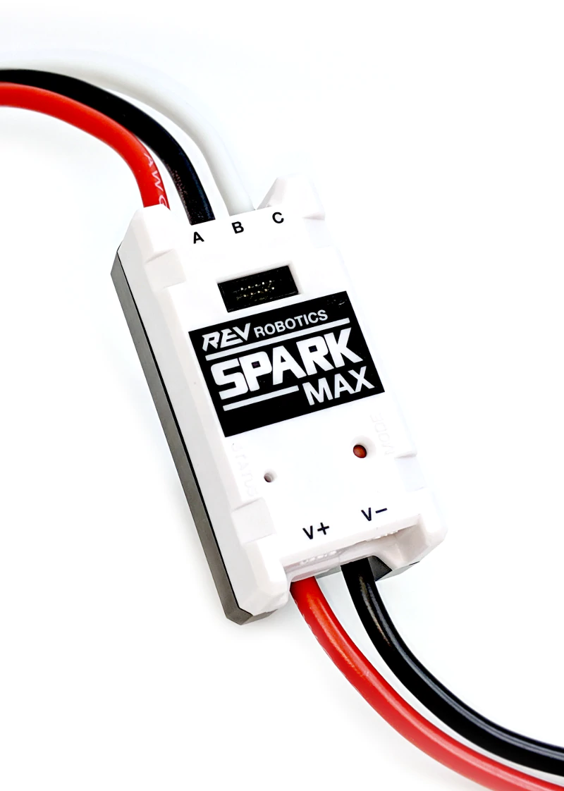
SPARK MAX is designed to drive 12V brushed and brushless DC motors at currents up to 60A continuously. Power and motor connections are made through the two sets of wires built into the SPARK MAX. The wires are 12AWG ultra-flexible silicone-coated wire. Each wire runs approximately 15cm from the end faces of the controller. Be sure to take care when cutting and stripping the wires as not to cut them too short. The figure below shows these connections in detail.
SPARK MAX Motor Controller Power Connections
As with any electrical component, make all connections with the power turned off. Connecting the SPARK MAX to a powered system may result in unexpected behavior an may pose a safety risk.
Motor Output
Motor output wires are labeled as A, B, and C with red, black, and white wires. Brushed motors must be connected to the A and B wires, while brushless motors must be connected to all three. It is critical that the order of the brushless motor wires match the SPARK MAX or the motor will not spin and could be damaged. Additional details are below.
Motor Connections
SPARK MAX cannot detect which motor type it is connected to. Be sure to configure the SPARK MAX to run the type of motor you have connected. See the Motor Type - Brushed/Brushless Mode section for more details on configuring the appropriate motor type.
Power Input
Power input wires are labeled as V+ and V- with red and black wires. The SPARK MAX is intended to operate in a 12 V DC robot system, however, it is compatible with any DC power source between 5.5 V and 24 V.
DO NOT reverse V+ and V- or swap motor and power connections. Doing so will cause permanent damage to the SPARK MAX and will void the warranty.
DO NOT exceed the maximum supply voltage of 30V. Doing so will cause permanent damage to the SPARK MAX and will void the warranty.
When using high-current motors, it is recommended to use a power source that is capable of handling large surge currents, e.g. a 12V lead-acid battery. If the supply voltage drops below 5.5V the SPARK MAX will brown out, resulting in unexpected behavior. It is also highly recommended to incorporate a fuse or circuit breaker in series with the SPARK MAX between it and the power source to prevent exceeding the maximum current rating.
DO NOT exceed the maximum current ratings:
60A for 3 minutes
Control Connections
The SPARK MAX can be controlled by three different interfaces, servo-style PWM, controller area network (CAN), and USB. The following sections describe the physical connections to these interfaces in detail. For details on the operation and protocols of the PWM, CAN, and USB interfaces, please see the .
The CAN/PWM Port is located on the power input side of the SPARK MAX. This port can be connected to either a servo-style PWM signal or a CAN bus with other devices. Connector details can be found below.
SPARK MAX Getting Started
The SPARK MAX is a motor controller that can control both Brushed DC and Brushless DC motors. Out of the box, the MAX defaults to its Brushless Mode and is ready to drive a NEO Brushless Motor with its PWM interface. Included in this section are the basic steps to get a motor spinning using the REV Hardware Client as well as information on how to configure your SPARK MAX.
We recommend following this guide in its entirety at least once to understand the key features of the SPARK MAX. This guide can also serve as a fallback in case of any issues faced.
Before You Start
Before following this guide, the before continuing. The client is the best way to verify that the device is configured correctly, and is requiredbefore using the CAN interface.
Wiring the SPARK MAX
Required Materials
12V Battery
120A Circuit Breaker
Power Distribution Panel
SPARK MAX
Brushed or Brushless Motor
USB Type-C Cable
Using a test bed is an easy way to get started with using the SPARK MAX and verify connections and code. For the initial bring up of the SPARK MAX a test bed with a single SPARK MAX, a brushless or brushed motor, and a is recommended.
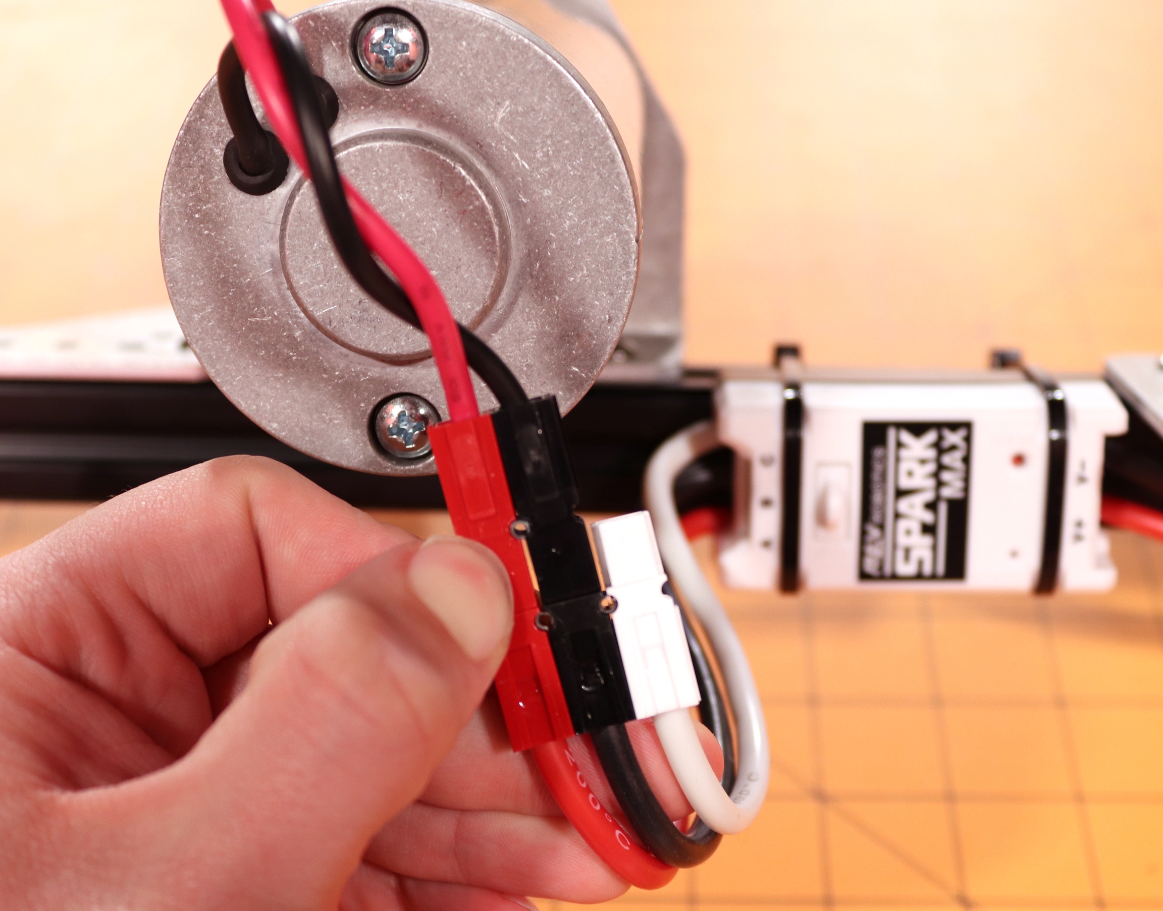
The power and motor wires are permanently connected to the SPARK MAX and are not replaceable. So take care not to cut these wires too short. It is highly recommended to install connectors on these wires to simplify both the power and motor connections. A common connector used for this purpose is the Anderson Power Pole connector. Follow our guide for tips on how to properly crimp these connectors.
Connect the integrated SPARK MAX power leads labeled V+ (red) and V- (black) to an available channel on the Power Distribution Panel. If you need to extend the length of the integrated wires, it is recommended to use 12AWG wire or larger (lower gauge number).
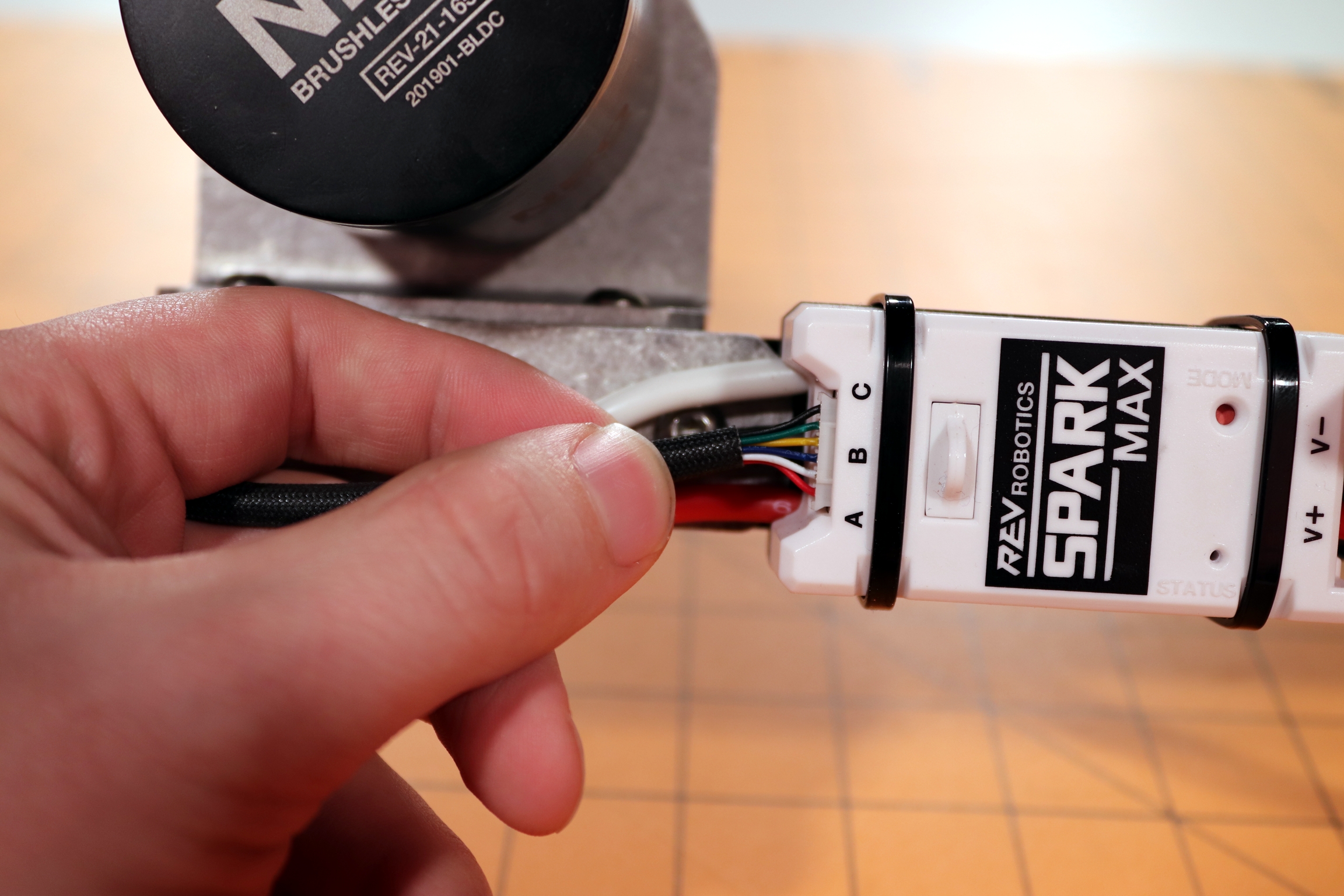
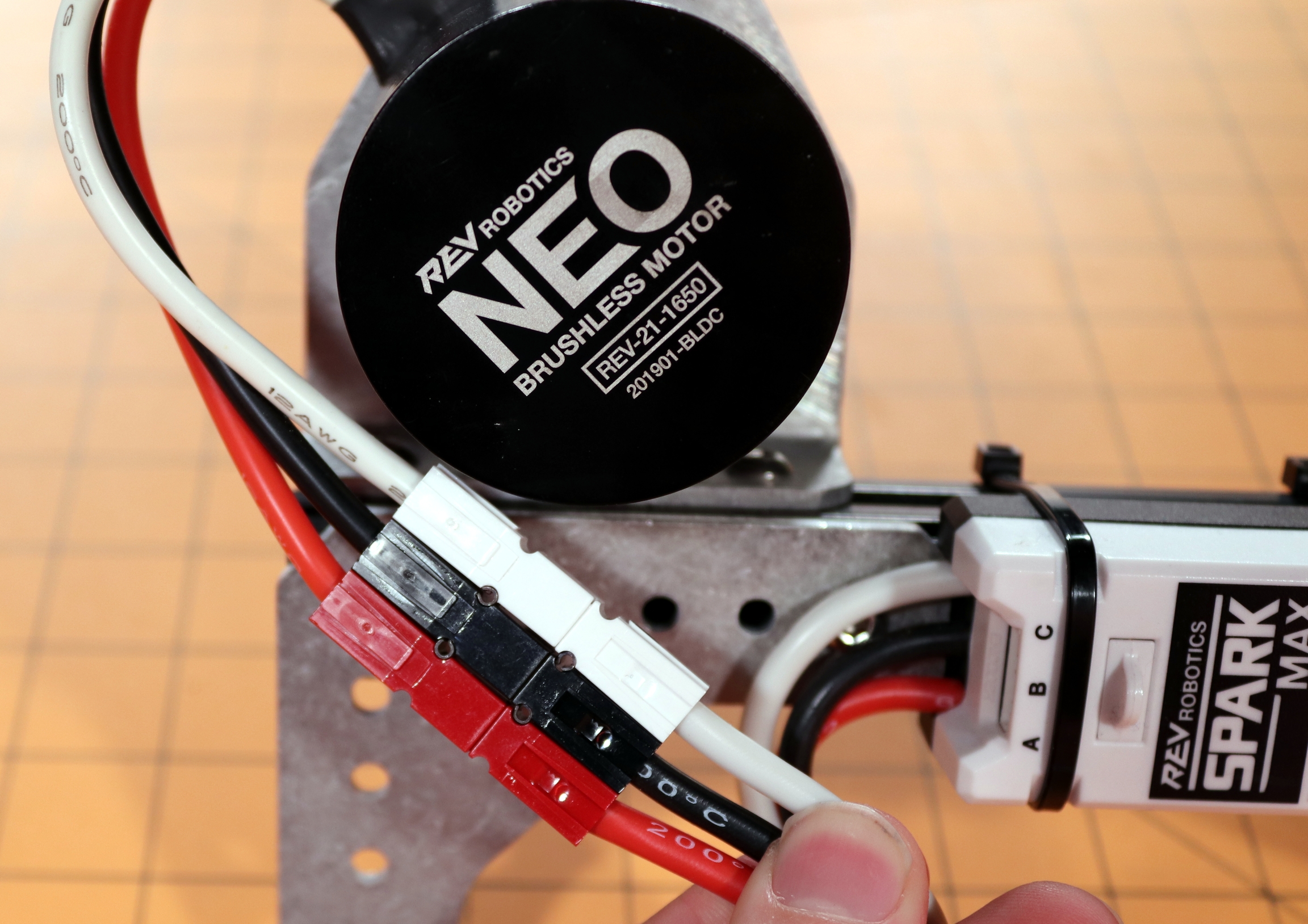
The first step is determining the type of motor you wish to connect. The SPARK MAX supports two types of motors: brushed DC and brushless DC. An easy way to determine the motor type is to look at the number of primary (larger) motor wires. Brushed motors only have 2 primary motor wires, while brushless motors have 3 primary wires and additional smaller sensor wires.
Connect the three motor wires; red, black, and white, to the matching SPARK MAX output wires labeled A (red), B (black), and C (white).
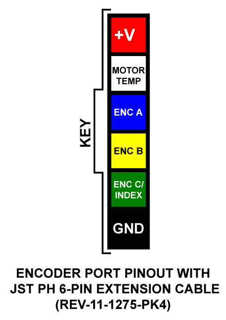
Next connect the NEO or NEO 550's encoder cable to the port labeled ENCODER just above the output wires.
Connect the two motor wires, M+ (red) and M- (black), to the SPARK MAX output wires labeled A (red) and B (black).
The third output wire, labeled C (white), is not used when driving a brushed motor and should be secured and insulated. We recommend tying it back with a zip-tie and covering the end with a piece of electrical tape. Do not cut this wire in case you wish to use a brushless motor in the future. In the example below the extra unused motor wire is insulated by the white connector and secured in the block.
Carefully check all connections before continuing and verify that all colors match. The SPARK MAX can be permanently damaged if the power connection is reversed.
SPARK MAX Operating Modes
Brushed and brushless DC motors require different motor control schemes based on the differences in their technology. It is possible to damage the SPARK MAX, the motor, or both if the appropriate motor type isn't configured properly.
Brushed or brushless motor types can be configured using the Mode Button, CAN, and USB interfaces.
Follow the steps below to switch motor types with the Mode Button. It is recommended that the motor be left disconnected until the correct mode is selected.
Connect the SPARK MAX to the main power, not just USB Power.
Absolute Encoders
The SPARK MAX does not need to be configured to a specific mode to accept input from an absolute encoder as long as the encoder is connected to the SPARK MAX Data Port.
Parameter
Specification
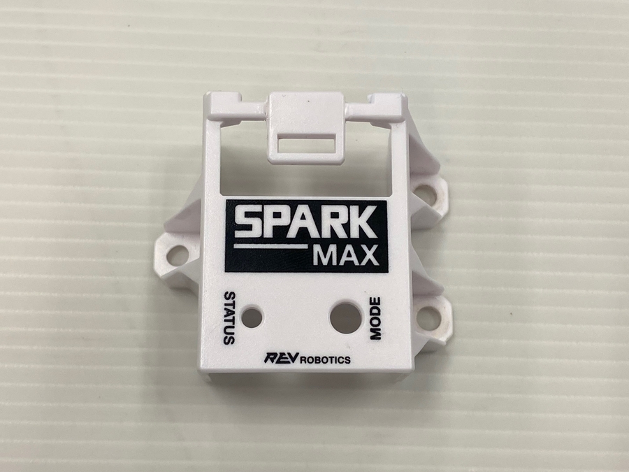
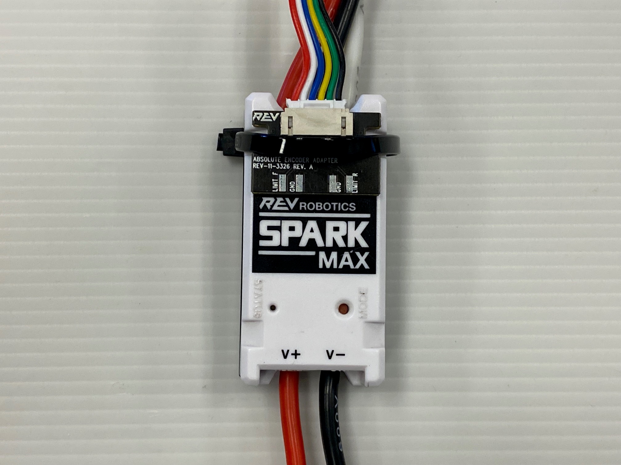
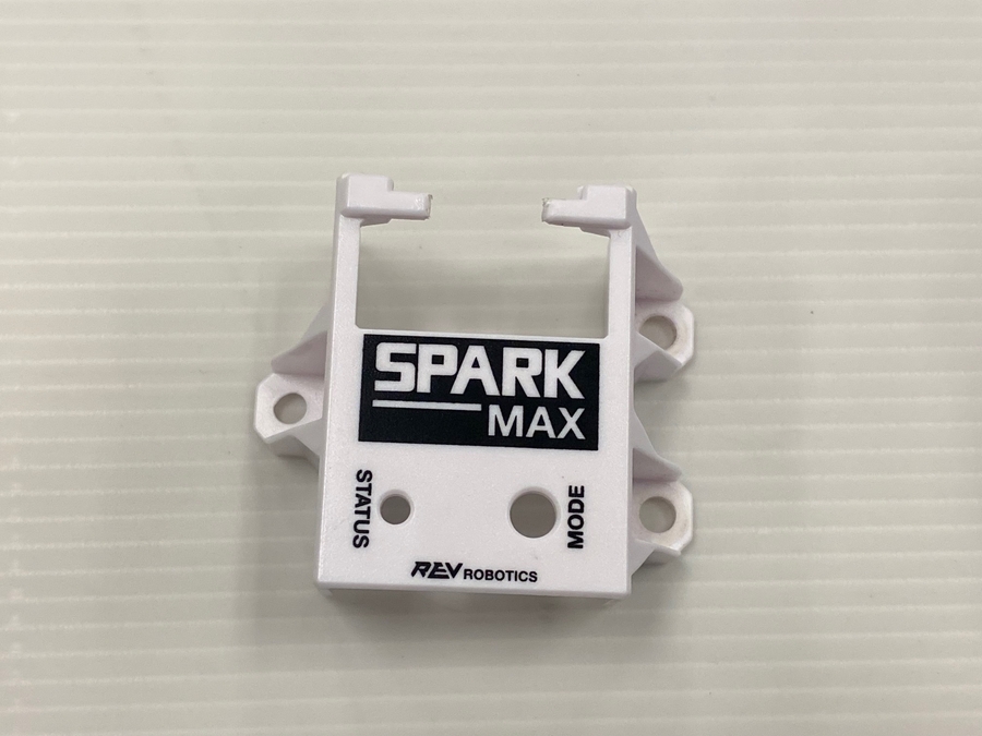
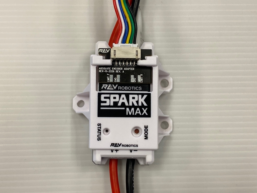
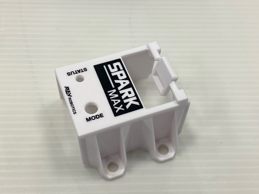
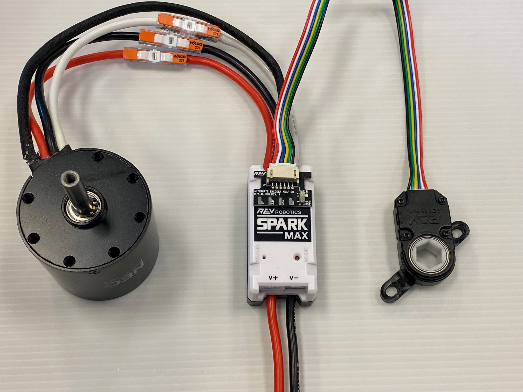
Securing the Encoder Adapters
The Encoder Adapters and SPARK MAX Data Port Breakout Boards can be secured to a SPARK MAX in two ways.
1) To use a SPARK MAX Mounting Bracket to secure your Encoder Adapter or Breakout Board you will need to remove the middle tab of plastic
2) Cut this piece of plastic with a pair of snips, or remove it by twisting the plastic until it breaks
3) Once the middle piece of plastic has been removed, remove any sharp edges with a file or some sandpaper
4) The SPARK MAX Mounting Bracket will fit over the board as shown in this image. Attach the mounting bracket to your surface as you normally would after this step
Zip-tie Notches
A zip-tie can be secured around the SPARK MAX's zip-tie notches and over the board to securely attach it to the motor controller as well.
Anderson Powerpole Connectors
Anderson Powerpole connectors are a popular choice in the FIRST community for electrical connections. Ensuring that these connectors are crimped properly and the contact is fully inserted into the housing is key to having a good electrical connection.
Anderson Powerpole Connectors consist of two major parts: the housing and contact. There are a number of different housings and contacts depending on the power requirements of the system. The most common housing and contact used with the SPARK MAX is the 1327 series housing paired with the 45 amp contacts.
Anderson Connector Housing
The housings for the connectors are genderless allowing all powerpole connectors to mate with themselves. The 1327 series housing can utilize contacts rated for 15-45 amps. Housings come in a variety of colors allowing for easy pairings with the wire color.
Dovetails on each housing allow them to slide together. Do not attempt to snap the housings together as they can break. After the housings are mated together adding a roll pin prevents the housings from become detached during operation. Each housing is fitted with a spring to retain the contacts after they are inserted
Anderson Contacts
1327 series housings can use contacts rated for between 15 and 45 amps. The 45 amp contacts are used with the SPARK MAX. When striping wire for the contact, make sure the stripped wire is the length of the large flap. No wire should extend past the large flap into the gap between the large and small flaps on the contact. Utilize a proper crimping tool when crimping on the connector.
Having too much wire exposed can cause issues with proper placement of the contact in the housing. This can lead to bad connections. If the contacts are not fully inserted into the housing the contact connection issues can arise. The images above are examples of good crimps with the proper amount of wire inserted into the contact.
Having improper placement of the contact in the housing can lead to intermittent brownouts of the SPARK MAX, the contact dislodging from the housing, or have cause problems with one or more of the phases of a brushless motor.
For more information on powerpole assembly see the Powerwerx instructions.
SPARK MAX Client
This is legacy documentation for our discontinued SPARK MAX Client Software. If you are interested in running a SPARK MAX via a computer, please see our newer documentation: Getting Started with the REV Hardware Client.
Update, configure, and test your SPARK MAX Motor Controller with the SPARK MAX Client application.
Latest SPARK MAX Client - Version 2.1.1
For instructions on how to access this legacy software, please email support@revrobotics.com
The SPARK MAX Client will not work with SPARK MAX beta units distributed by REV to the SPARK MAX beta testers. It is only compatible with units received after 12/21/2018.
System Requirements
Windows 10 64-bit
Windows 7 64-bit might work but it is not supported.
Internet connection for automatic updates
Installation Instructions
Download the SPARK MAX Client installer above.
Run the installer. Windows may require approval to install the application.
During the installation process, separate driver installation windows may appear. Some driver installations may fail if you already have the driver installed from a previously installed Client, this is expected.
Once installed, run the application. If prompted, be sure to grant network access. Without network access, the client software won't be able to download the latest SPARK MAX firmware and client updates.
Navigating the SPARK MAX Client
The Navigation bar is visible on all tabs of the SPARK MAX Client and allows you to select with SPARK MAX the Client is connected to.
Identify Device: The status LED of a selected device will blink. This is helpful when troubleshooting or configuring multiple devices.
Device Selection: See each SPARK MAX connected to the SPARK MAX Client. This includes other devices connected via CAN if running firmware 1.4.0 or later.
Updating Device Firmware
Follow the steps below to update the firmware on your SPARK MAX:
Connect your SPARK MAX Motor Controller to your computer with a USB-C cable.
Open the REV SPARK MAX Client application.
SPARK MAX Client Troubleshooting
If this is the first time installing the SPARK MAX Client or connecting a SPARK MAX in Recovery Mode, you may see an error the first time you try to update firmware on your computer. The DFU driver is one of two drivers installed by the Client and is used for updating firmware. It may not install completely until a SPARK MAX in DFU Mode (Recovery Mode) is plugged into the computer.
If you see an error during your first firmware update, please do the following:
Doing so will cause permanent damage to the SPARK Flex and will void the warranty.
Holding a constant torque requires the current applied to the motor windings (or motor phases) to remain constant, despite these changes due to heat. Therefore, it is useful to know the time to failure of a motor at different currents rather than different voltages.
The SPARK MAX Motor Controller includes a Smart Current Limit feature that can adjust the applied output to the motor to maintain a constant phase current. Below you will find data at various current levels being maintained in the NEO 550 Brushless Motor.
Please take the following into consideration when interpreting the data below:
Average motor phase current (or winding current) is different than the average input current to the motor controller.
Average Input Current = Average Phase Current x Duty Cycle
Motor torque is proportional to phase current, not the input current. Therefore, it is important to control the phase current and not the input current.
The torque values in the graphs are approximate and are measured using a digital torque wrench which includes an error up to ~5%. The intent is to show the point of failure and not the torque/current relationship. Please see each motor's documentation page for its torque and current specifications.
At higher current limits, the time-to-failure depends on many different factors. It is best practice to design mechanisms with a considerable safety margin.
Locked-rotor test setup:
The motor is mounted to an aluminum motor bracket at the face plate with the output shaft locked in place through a digital torque wrench.
SPARK MAX is controlling the motor and its Smart Current Limit is configured to the desired limit for the test. It is then commanded to go full-power while letting the Smart Current Limit adjust the applied output duty cycle as necessary to keep the phase current at the limit.
The intent of this graph and the graphs below is to show an approximate time-to-failure at various current limits. Various factors can affect these times and, as always, mechanisms should be designed with a considerable margin.
These stall times are not guaranteed.
Download the raw data in CSV format:
The intent of this graph and the graphs below is to show an approximate time-to-failure at various current limits. Various factors can affect these times and, as always, mechanisms should be designed with a considerable margin.
These stall times are not guaranteed.
Time to Failure Summary
20A Limit - Motor survived full 220s test.
40A Limit - Motor failure at approximately 27s.
60A Limit - Motor failure at approximately 5.5s
80A Limit* - Motor failure at approximately 2.0s
*80A is the default Smart Current Limit in the SPARK MAX. It is highly recommended to adjust the Smart Current Limit when driving the NEO 550.
What is Locked Rotor Testing?
Constant Current vs. Constant Voltage
Locked-rotor Testing with SPARK MAX Smart Current Limit
Locked Rotor Testing Data
1/2 in Hex Shaft - Any Length ()
The NEO Vortex's 1/2in hex through-bore motor spindle is compatible with any length hex shaft.
Vortex Shaft - 15T Spline ()
The Vortex Shaft - 15T Spline, compatible with the , gives users the ability to drive inputs that have a 8mm diameter involute 15T spline. Compatible with SplineXS shaft components.
Vortex Shaft - 8 mm ()
The 8mm Vortex Shaft, compatible with the , empowers you to utilize the NEO Vortex Brushless Motor with any 8mm keyed shaft component. This interchangeability also means that the NEO Vortex matches the output of a , making it a seamless drop-in replacement for your designs.
Vortex Shaft - MAXSwerve Integrated Key ()
The Vortex Shaft - MAXSwerve Integrated Key gives users the ability to drive a MAXSwerve Module without the need for the MAXSwerve Key. This eliminates a potential point of failure in the MAXSwerve since the key is machined directly into the 8mm shaft.
Vortex Shaft - 20 DP Gear - 7T
()
The Vortex Shaft - 20 DP Gear - 7T offers users the unique ability to achieve substantial gear reductions directly from the motor. This gear features a 7T 20 DP design that is typically too small for an 8mm keyed input. However, it becomes possible when integrated into the motor shaft.
The Vortex Shaft - 20 DP Gear - 7T is addendum shifted to an 8 T pitch diameter. This allows you to calculate center-to-center distances as if it were an 8T gear rather than a 7T.
The Vortex Shaft - 20DP Gear - 8T offers users the unique ability to achieve substantial gear reductions directly from the motor. This gear features a 8T 20DP design that is typically too small for an 8mm keyed input. However, it becomes possible when integrated into the motor shaft.
Vortex Shaft - MAXPlanetary Input Kit
()
Working seamlessly with the MAXPlanetary Vortex Input Stage, the Vortex Shaft - MAXPlanetary Input Coupler reduces gearbox length for more efficient designs. Note that the MAXPlanetary Vortex Input Stage is required for this setup.
Vortex Shaft - Falcon Compatible Spline ()
The Vortex Shaft - Falcon Compatible Spline gives users the ability to drive components that have a falcon spline bore.
NEO Vortex Shaft Anatomy
NEO Vortex Shaft Options
Parts of a NEO Vortex Shaft
Duty Cycle or PWM
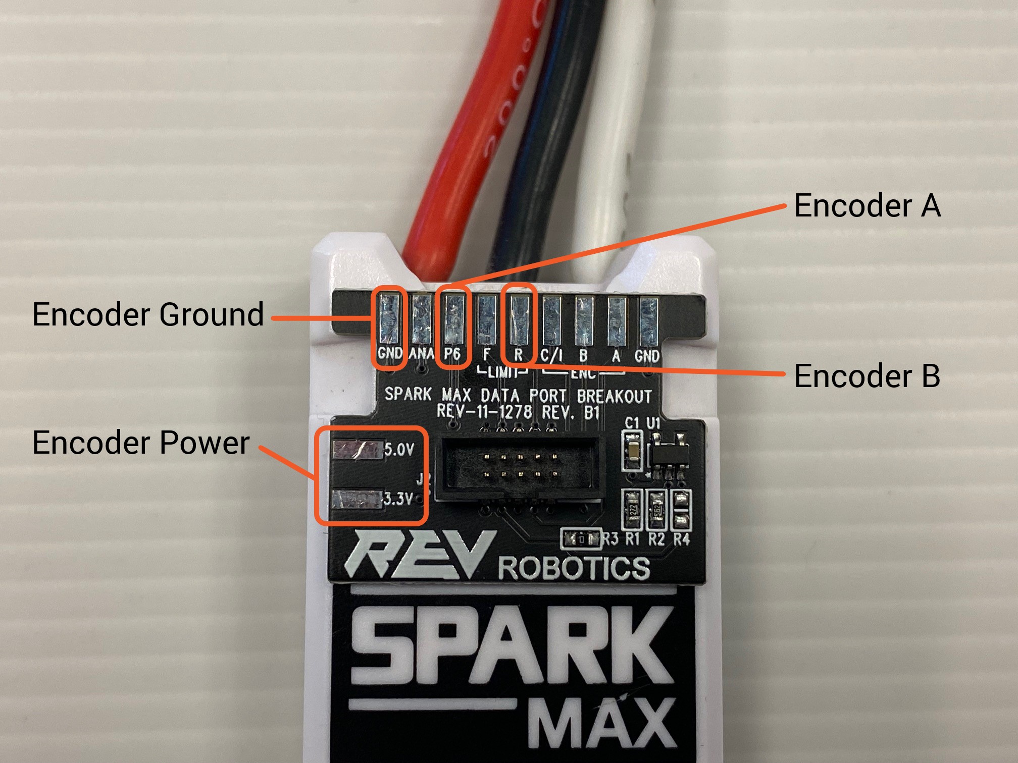
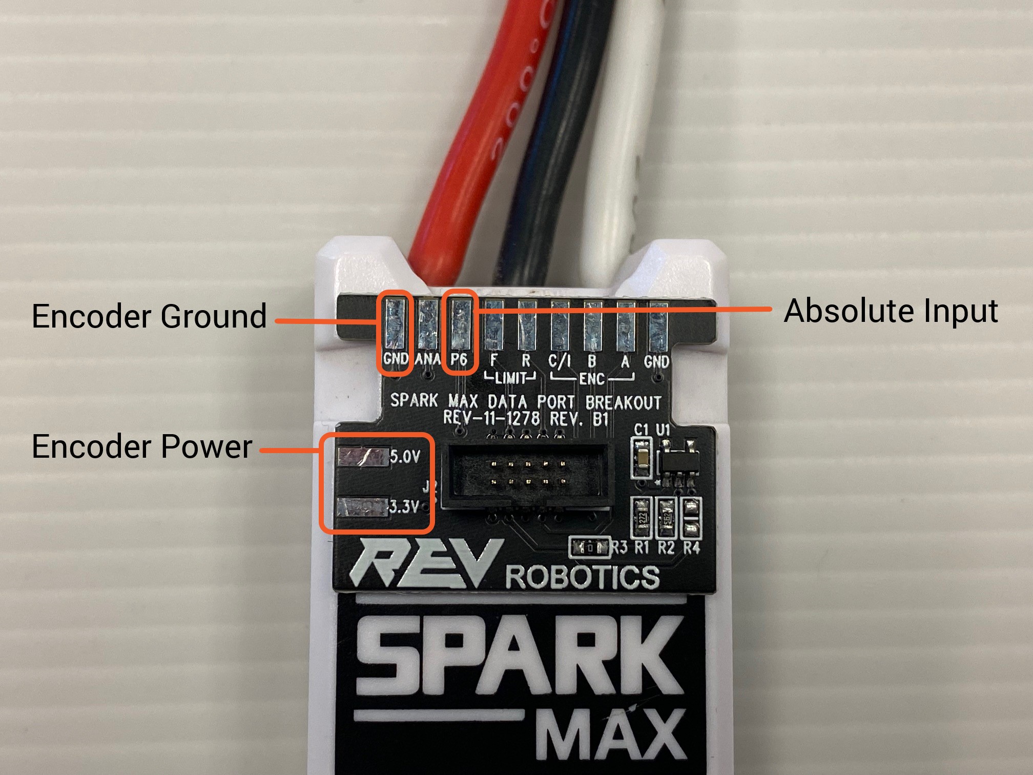
Connecting an absolute encoder that is not a Through Bore Encoder will likely require a custom wiring harness or SPARK MAX Data Port Breakout Board to connect the necessary encoder power, ground, and signals to the SPARK MAX Data Port. When using an Absolute Encoder use the following pinout information for the Data Port:
Connector Pin
Pin Type
Pin Function
1
Power
+3.3V
2
Encoder Output Voltage Level
5.0V
Absolute Encoder Specifications
Encoder Type Supported
Absolute encoder input is supported by SPARK MAX Firmware Version 1.6.0 and newer,
Connecting an Absolute Encoder
Data Port Connector Information
The Client should automatically scan and connect to your SPARK MAX. If your SPARK MAX is running outdated firmware, you will be notified with a pop-up window like the one pictured below:
Click Open Network Tab & Scan Bus and proceed to the next step.
Your SPARK MAX should now be listed in the device list. Click the checkbox next to the SPARK MAX you wish to update, and click Load Firmware.
Select the latest firmware file in the firmware directory that the client created on startup. If there isn't a firmware directory, you can also navigate to a file that was downloaded manually. Click Open once the appropriate firmware file is selected:
Click Yes to confirm the update.
Once complete, the Client will rescan the bus and display the updated controllers.
SPARK MAX Firmware Version 1.5.0 includes a USB-to-CAN Bridge feature that allows a single USB-connected SPARK MAX to act as a bridge to the entire CAN bus it is connected to. This allows for configuration and simultaneous updating of multiple SPARK MAX controllers without having to connect to each one individually. Using this feature requires the following:
A USB-connected SPARK MAX that is updated to firmware version 1.5.0 or newer to act as the Bridge.
Other SPARK MAXs connected on the CAN bus must be individually updated to firmware version 1.4.0 before they are able to receive mass-updates from the Bridging SPARK MAX.
Once these requirements are satisfied, navigate to the Network tab, select the controllers you wish to update, and follow the same firmware update procedure described above starting at Step 4.
When complete, the Client will display the number of successfully updated controllers.
If a controller fails to update it is usually due to the process being interrupted by a bad power or CAN connection. Severe interruptions can cause the firmware update to be corrupted. A corrupted controller can no longer be updated over the USB-to-CAN Bridge, however, it can be recovered by connecting to the controller directly over USB and putting it in Recovery Mode.
This is legacy documentation for our discontinued SPARK MAX Client Software. If you are interested in running a SPARK MAX via a computer, please see our newer documentation: Getting Started with the REV Hardware Client.
Updating a Single Device
If your SPARK MAX is running firmware older than 1.4.0, you may not see a pop-up and will need to proceed directly to the Network tab and click Scan Bus manually.
If your SPARK MAX is listed and you are unable to click the checkbox next to it, you must put your SPARK MAX into .
Updating Multiple Devices with the USB-to-CAN Bridge
The Status LED will indicate which motor type is configured by blinking yellow or blue for Brushed Mode or blinking magenta or cyan for Brushless Mode.
Press and hold the Mode Button for approximately 3 seconds.
After the button has been held for enough time, the Status LED will change and indicate the different motor configuration.
Release the mode button.
Follow the steps below to switch motor types with the USB and the REV Hardware Client application. Be sure to application before continuing.
Connect the SPARK MAX to your computer using a USB-C cable.
Open the REV Hardware Client and verify that the application is connected to your SPARK MAX.
On the Basic tab, select the appropriate motor type under the Select Motor Type menu.
Click Burn Flash and confirm the change.
Please see the for information on how to configure the SPARK MAX using the CAN interface.
When the SPARK MAX is receiving a neutral command the idle behavior of the motor can be handled in two different ways: Braking or Coasting.
When in Brake Mode, the SPARK MAX will effectively short all motor wires together. This quickly dissipates any electrical energy within the motor and brings it to a quick stop.
When in Coast Mode, the SPARK MAX will effectively disconnect all motor wires. This allows the motor to spin down at its own rate.
The Idle Mode can be configured using the Mode Button, CAN, and USB interfaces.
Follow the steps below to switch the Idle Mode between Brake and Coast with the Mode Button.
Connect the SPARK MAX to main power, not just USB Power.
The Status LED will indicate which Idle Mode is currently configured by blinking blue or cyan for Brake and yellow or magenta for Coast depending on the motor type.
Press and release the Mode Button
You should see the Status LED change to indicate the selected Idle Mode.
Follow the steps below to switch the Idle Mode between Brake and Coast with the USB and the REV Hardware Client application. Be sure to application before continuing.
Connect the SPARK MAX to your computer using a USB-C cable.
Open the REV Hardware Client application and verify that the application is connected to your SPARK MAX.
On the Basic tab, select the desired mode with the Idle Mode switch.
Click Burn Flash and confirm the change.
Please see the for information on how to configure the SPARK MAX using the CAN interface.
Brushed/Brushless Mode - Motor Type
Mode Button Configuration
Use a small screwdriver, straightened paper clip, pen, or other small implement to press the button. Do not use any type of pencil as the pencil lead can break off inside the SPARK MAX.
Please see the guide for information on how to identify the Motor Type configuration by the color of the Status LED!
USB Configuration
CAN Configuration
Brake/Coast Mode - Idle Behavior
Mode Button Configuration
Use a small screwdriver, straightened paper clip, pen, or other small implement to press the button. Do not use any type of pencil as the pencil lead can break off inside the SPARK MAX.
Please see the guide for information on how to identify the Idle Behavior configuration by the color of the Status LED!
USB Configuration
CAN Configuration
1
CAN High
Signal
2
CAN Low
Ground
3
CAN High
Signal
4
CAN Low
Ground
Description
Manufacturer
Part Number
Vendor
Vendor P/N
JST-PH 4-pin Housing
JST
PHR-4
Identical-function pins are electrically connected inside the SPARK MAX, therefore the CAN daisy-chain is completed internally and any two signal and ground pairs can be used for PWM.
The USB-C Port is located on the power input side of the SPARK MAX. It supports USB 2.0 and 5V power for the SPARK MAX's internal microcontroller. While you can configure the SPARK MAX without main power, you will not be able to spin a motor.
Rescan: Looks for additional SPARK MAX devices connected to the SPARK MAX Client. This includes other devices connect via CAN if running firmware 1.4.0 or later.
Connect/Disconnect: After selecting a device connecting to the device pulls all the configuration parameters set on the device.
Tabs: Select one of the five tabs to gain access to configure, update, and run SPARK MAX.
The Basic Tab is used to set the most common parameters for the SPARK MAX
Configurations: This drop down allows you to select pre-existing configurations store on the Windows machine running the SPARK MAX Client or to pull the existing parameters stored on in RAM on the SPARK MAX. This is helpful when configuring multiple motor controllers to the same settings.
CAN ID: This assigns a SPARK MAX a CAN ID for identification over the CAN BUS. Any configured SPARK MAX must have a CAN ID.
Configured Parameters: Change the motor type, sensor type, idle mode behavior, and more.
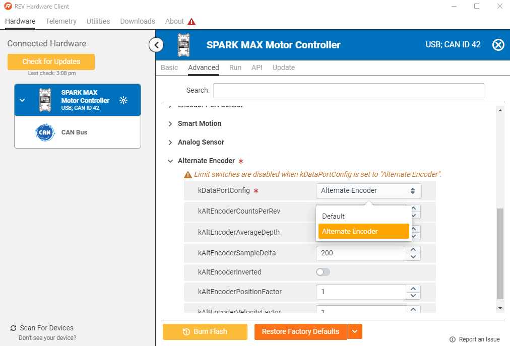
The Advanced Tab allows for changing all configurable parameters of the SPARK MAX without needing to set them in code.
Search Parameters: Allows for easy look up of a specific parameter for editing.
Parameter Table: Select the arrow to show all configurable parameters within a specific group. For more information on each parameter type see Configuration Parameters.
The Run Tab allows for the SPARK MAX to operate over USB or a USB to CAN Bridge without the need for a full control system. This is helpful for testing mechanisms and tuning their control loops.
Bar Select: Select from either run, parameters, or signals to provide information and feedback when operating SPARK MAX.
Signal Chart: Shows any added signals in graph form when running a SPARK MAX. This is helpful when tuning control loops.
PIDF: Update PIDF parameters on the fly to tune control loops on the SPARK MAX.
Run: Choose setpoints to run a motor connected to a SPARK MAX using various modes, including position, velocity, and duty cycle.
The Network Tab shows all connected devices via USB and the USB to CAN interface. From the Network Tab each device can be identified and firmware updated.
Device Select: Select a device to update firmware.
Load Firmware: Select what firmware to update onto selected devices.
This is legacy documentation for our discontinued SPARK MAX Client Software. If you are interested in running a SPARK MAX via a computer, please see our newer documentation: Getting Started with the REV Hardware Client.
Navigation Bar
Basic Tab
Advanced Tab
Run Tab
The three icons for bar select change the bottom third of the Run Tab for configuration. Once signals and other parameters are configured selecting the run bar icon will allow for running of a motor with the SPARK MAX Client.
Network Tab
For more information on the firmware updating process see for both and updates.
Follow the steps below to switch the Idle Mode between Brake and Coast with the Mode Button.
Connect the SPARK Flex to main power, not just USB Power.
The Status LED will indicate which Idle Mode is currently configured by blinking blue or cyan for Brake and yellow or magenta for Coast depending on the motor type.
Press and release the Mode Button
You should see the Status LED change to indicate the selected Idle Mode.
Follow the steps below to switch the Idle Mode between Brake and Coast with the USB and the REV Hardware Client application. Be sure to download and install the REV Hardware Client application before continuing.
Connect the SPARK Flex to your computer using a USB-C cable.
Open the REV Hardware Client application and verify that the application is connected to your SPARK Flex.
On the Basic tab, select the desired mode with the Idle Mode switch.
Click Update Configuration and confirm the change.
Please see the API Information for information on how to configure the SPARK Flex using the CAN interface.
In the rare case where a firmware update has been interrupted or corrupted, it may be necessary to boot the SPARK Flex into Recovery Mode. This can be done by following the steps below. Have a computer running the REV Hardware Client and a USB cable ready in order to reload the device firmware once the device is in Recovery Mode.
Start with all power disconnected from the SPARK Flex.
Press and hold the Mode Button.
While still holding the Mode Button, connect power by either turning on main power or connecting the USB cable between the SPARK Flex and the computer.
Once powered, you may release the Mode Button. The LED should stay dark. The SPARK Flex is now in Recovery Mode.
If the firmware is not booting properly, it may not be easy to know if the device has entered Recovery Mode since the LED will be dark in both cases. To confirm that the SPARK Flex is in Recovery Mode:
Connect the USB cable between the SPARK Flex and computer if not already connected.
In the REV Hardware Client, the SPARK Flex should show up as a Recovery Mode Device when scanning for devices.
If the device doesn't show up, please repeat the process, ensuring that the power and button holding sequence is followed exactly. If the device still doesn't show up, please contact REV Support.
Brushed/Brushless Mode - Motor Type
Brake/Coast Mode - Idle Behavior
Mode Button Configuration
Please follow the before continuing.
Use a small straightened paper clip or other small blunt tool to press the button. Never use a sharp tool or any type of pencil, as the pencil lead can break off inside the SPARK Flex.
Please see the for information on how to identify the Idle Behavior configuration by the color of the Status LED!
USB Configuration
CAN Configuration
Recovery Mode
Please follow the before continuing.
Use a small straightened paper clip or other small blunt tool to press the button. Never use a sharp tool or any type of pencil, as the pencil lead can break off inside the SPARK Flex.
Use the REV Hardware Client to run the SPARK Flex over USB.
Please be aware of the CAN lockout feature of the SPARK Flex. If it has been connected to the roboRIO's CAN bus, a safety feature within the SPARK Flex will lock out USB communication. Disconnecting from the CAN bus and power cycling the MAX will release the lock.
If this is your first time running the REV Hardware client, see the for a tour of the software and its features.
Rule out a code issue:
Create a simple test program using our SPARK Flex Example Code.
Rule out a mechanical issue:
Remove the motor from the mechanism or use a different, free-spinning motor.
An extremely useful set of tools can be found on the Driver Station:
Higher than expected current on a channel can indicate both mechanical and electrical issues.
Look at the battery voltage:
Large dips in the battery voltage around the time of an issue can indicate battery health issues that cause brownouts.
Use the
Look at the CAN Bus Utilization.
Look at CAN Faults.
Look at Comms Faults:
It is also very useful to log or plot operating values internal to the SPARK Flex. These values can be accessed using the SPARK Flex APIs. Useful values to log:
getAppliedOutput()
This value will show what the SPARK Flex is actually applying to the motor output. This can illuminate issues with closed-loop control tuning.
getOutputCurrent()
This value will show the output current going to the phases of the motor. Output current won't always be the same as the Input current measured by the PDP. Knowing the output current is useful to diagnose current-limit issues if motors are overheating.
getBusVoltage()
A way to measure the input voltage right at the controller.
getStickyFaults()
A sticky fault indicates if a fault has occurred since the last time the faults were reset. Checking these can provide a lot of insight into what the controller is experiencing.
Sometimes, when updating the firmware on a SPARK Flex, it is possible for the process to be interrupted or for the firmware to be corrupted by a bad download or other type of interruption in data transfer. In this state, the Status LED will be dark or dim and the device will fail to operate. There is a built-in recovery mode that can force your device to accept new firmware even if the controller seems to be bricked and the procedure is outlined below:
Please note, that performing this procedure will erase all data and settings on the device. To perform the procedure a small tool, like a straightened paper clip, is necessary to press the Mode Button (located to the right of the Status LED), the orange USB-C cable that came with the unit (or a DATA capable USB-C cable), and a native Windows based computer with the REV Hardware Client installed:
With the SPARK Flex disconnected from power, press and hold the Mode Button.
While still holding the Mode Button, connect the Device to the computer using the USB-C cable - the Status LED will not illuminate - this is expected.
With the REV Hardware Client running on the computer, wait a few seconds for the audible tone or icon for the device to be recognized in recovery mode then release the Mode Button - no lights will be present on the SPARK Flex during this stage of the process, this is expected.
Select the SPARK Flex in Recovery Mode from the REV Hardware Client window.
From the "Choose a Device" type dropdown, choose - SPARK Flex.
Choose the latest version of the firmware from the dropdown and then click update.
Wait for the software update to complete.
Power cycle unit (unplug and plug in USB-C) click on the SPARK Flex icon, and clear any sticky faults - the recovery should be complete!
General Troubleshooting Tips
Rule Out Issues By Isolation
Use the Driver Station
Use the APIs
CAN Troubleshooting
Recovery Mode
Plug the SPARK MAX back into the computer.
Open the Client application.
Alternatively, you can preemptively finalize the DFU driver installation by following the Recovery Mode steps before using the Client for the first time.
We are aware of this issue and will release a fix in a future update of the SPARK MAX Client.
As we get feedback from users and identify exact causes for issues, please look back here for troubleshooting help. If you are running into issues running the SPARK MAX Client try the following BEFORE contacting support@revrobotics.com:
Try running the SPARK MAX Client as an Administrator
Make sure that Windows is fully up-to-date. Some computers have Windows Update disabled and need to be updated manually.
Check the Device Manager and verify that the SPARK MAX shows up as one of the following two devices with no caution symbols:
Normal operating mode: Device Manager -> Ports (COM & LPT) -> USB Serial Device (COMx)
Recovery mode: Device Manager -> Universal Serial Bus Controllers -> STM Device in DFU Mode
If the device shows up with errors or as STM32 BOOTLOADER, try installing the separately.
This is legacy documentation for our discontinued SPARK MAX Client Software. If you are interested in running a SPARK MAX via a computer, please see our newer documentation: Getting Started with the REV Hardware Client.
Error During First-time Firmware Update
Troubleshooting
Prepare the Components
Test Bed
Electrical Connections
Make sure the power is disconnected or turned off before making any electrical connections on your test bed or robot.
Motor Connections
NEO Brushless Motor Connections
The encoder sensor cable is requiredfor the operation of brushless motors with SPARK MAX. The motor will not spin without it.
Brushed DC Motor Connections
Verify Connection
Leave the CAN cable disconnected for now, we will wiring this up later.
The REV NEO Brushless Motor (REV-21-1650) is the first brushless motor designed to meet the unique demands of the FRC community. Offering an incredible power to weight ratio along with it's compact size it's designed to be a drop-in replacement for CIM-style motors as well as an easy install with mounting options.
Features
Drop-in replacement for CIM-style motors
Shielded out-runner construction
Front and rear ball bearings
High-temperature neodymium magnets
High-flex silicone motor wires
Integrated motor sensor
3-phase hall sensors
Motor temperature sensor
Connecting the NEO V1.1 Brushless motor is fairly straightforward. Follow the guide at, and don't forget to connect your sensor wire; the motor will not spin without it!
Parameter
Value and Units
Parameter
Value and Units
NEO 550
NEO 550 Overview
The REV NEO 550 Brushless Motor (REV-21-1651) is the newest member of the NEO family of brushless motors. Its output power and small size are specifically designed to make NEO 550 the perfect motor for intakes and other non-drivetrain robot mechanisms. Mounting holes and pilot match a standard 550 series motor, allowing it to natively mount to many existing off-the-shelf gearboxes.
The REV NEO 550 Brushless Motor runs a 0.12in output shaft which, when combined with its 550-style mounting features, allows for easy installation in many off-the-shelf gearboxes.
Its small size and weight make it easy to put power where you need it, whether that is on intakes, end-effectors, or other weight-sensitive mechanisms. However, keep in mind that this motor has a lower thermal mass than a NEO, CIM, or Mini CIM, and thus it may not be ideal for some drivetrain applications.
Wiring Connections
Connecting the NEO 550 Brushless motors is fairly straightforward. Follow the guide at Wiring the Spark Max, and don't forget to connect your sensor wire; the motor will not spin without it!
CAUTION: Improperly wiring the connectors can cause severe motor damage and is not covered by the warranty. DO NOT connect the motor directly to the battery.
Features
Mounting features match other 550 series DC motors
Out-runner construction
Front and rear ball bearings
High-temperature neodymium magnets
High-flex silicone motor wires
Integrated motor sensor (3-phase hall sensors)
Motor temperature sensor
Parameter
Value and Units
Parameter
Value and Units
NEO Vortex Solo Adapter
The NEO Vortex Solo Adapter (REV-11-2828), allows teams to seamlessly integrate the NEO Vortex Brushless Motor with a SPARK MAX. This adapter breaks out the motor sensor connector and phase wire connections for simple backward compatibility.
While the NEO Vortex Solo Adapter allows you to use the motor independently, it may not fully support certain advanced functionalities of the NEO Vortex Brushless Motor.
Specifications
Parameter
Value and Units
Phase Wire Gauge
The following items are included with each NEO Vortex Solo Adapter
SKU
Product Name
QTY
When docked with a NEO Vortex Solo Adapter a NEO Vortex can be controlled with a SPARK MAX.
Docking the NEO Vortex with the SPARK Flex is simple and only requires the following materials and tools:
NEO Vortex Brushless Motor
NEO Vortex Solo Adapter
Docking Hardware
4 - M3 x 25 mm Socket Head Screws (included with SPARK Flex)
Follow these steps to ensure a secure and proper docking:
Ensure that power is disconnected from the NEO Vortex Solo Adapter.
Align the motor phase bullets between the NEO Vortex and NEO Vortex Solo Adapter.
Allowing the bullets to guide the two together, press the NEO Vortex and NEO Vortex Solo Adapter together until their bodies meet. There may be a small gap between the motor and the controller opposite the bullets. This is normal.
Follow these steps to undock the NEO Vortex and NEO Vortex Solo Adapter:
Ensure that power is disconnected from the NEO Vortex Solo Adapter.
Completely remove the four docking screws from the assembly.
Gently pull the NEO Vortex and NEO Vortex Solo Adapter apart until the bullets release. Try to maintain their relative orientation to each other while pulling them apart.
The mounting face of the NEO Vortex Solo Adapter features six #10-32 threaded mounting holes on a 2 in bolt circle. Each hole has an absolute maximum depth of 0.25 in.
Similar to the SPARK Flex, the NEO Vortex Solo Adapter has depth gauges laser-etched into body to make it easy to check that the chosen screw length will not violate the maximum depth.
Just like you would with a SPARK Flex, simply check the screw length against the intended stack-up of structure and motor controller, and verify that it does not violate the maximum depth.
Pinion Pressing Guides
NEO V1.1 Pinion Pressing Guide
Needed Materials
NEO V1.1 (REV-21-1650)
1 - 10-32 x 3/8in long Socket Head Screw
Press Fit Pinion
Arbor Press
NEO V1.0 (REV-21-1650)
A high-quality 1.5mm Allen Key (i.e. WERA Tools, Bondhus)
Loctite 242
SPARK MAX Overview
SPARK MAX Resources
The REV Robotics SPARK MAX Motor Controller (REV-11-2158) is an all-in-one USB, CAN, and PWM enabled motor controller that can drive both 12 V brushed and 12 V brushless DC motors. SPARK MAX is designed for use in the FIRST Robotics Competition (FRC), incorporating advanced motor control in a small, easy-to-use, and affordable package. Configure and run the SPARK MAX through its built-in USB interface without needing a full control system.
Feature Summary
Brushed and sensored-brushless motor control
PWM, CAN, and USB control interfaces
PWM/CAN - Locking and keyed 4-pin JST-PH
USB - USB type C
USB configuration and control
Rapid configuration with a PC
Smart control modes
Closed-loop velocity control
Closed-loop position control
Encoder port
Locking and keyed 6-pin JST-PH
3-phase hall-sensor encoder input
Data port
Limit switch input
Quadrature encoder input with index
Mode button
On-board motor type and idle behavior configuration
RGB status LED
Detailed mode and operation feedback
Integrated power and motor wires
12 AWG ultra-flexible silicone wire
Passive cooling
The following items are included with each SPARK MAX Motor Controller
1 - SPARK MAX Motor Controller
1 - USB-A male to USB-C cable
1 - 4-pin JST-PH to CAN cable
We appreciate the assistance from the community for feedback, contributions, and testing the SPARK MAX, especially .
Make it Spin!
For REV Hardware Client 2 is available.
Power On
Now that the device is wired, and the connections carefully checked, power on the robot. You should see the SPARK Flex slowly blinking its for a new device the color will be Magenta. If the LED is dark, or you see a different blink pattern, refer to the Status LED guide for troubleshooting.
If you are using a brushed motor, you may see a sensor error. This is expected until you configure the device to accept a brushed motor in the following steps.
Connect to the SPARK Flex
Plug in the USB cable and start the REV Hardware Client. Select the SPARK Flex from the Connected Hardware
If you cannot see the SPARK Flex, make sure that the SPARK Flex is not being used by another application
. Then unplug the SPARK Flex from the computer and plug it back in.
Basic Setup and Configuration
Before any parameters can be changed, you must first assign a unique CAN ID to the device. This can be any number between 1 and 63. After setting a unique CAN ID, the user interface will refresh and allow you to change other parameters.
Eventually you may set up a CAN network on your test bench or robot. Be sure each device on the network has a unique CAN ID. It is helpful to label each device with its ID number to aid in troubleshooting.
Set the Motor Type
If you are using a NEO Vortex, NEO, or NEO 550, verify that the motor type is set to REV NEO Brushless, Sensor Type is Hall Effect, and the LED is blinking Magenta or Cyan.
Your ideal current limit may vary based on your specific application, but these values can be used as a starting point to reduce the chance of an overload on your motor as you begin tuning your specific mechanism's Smart Current Limit.
Motor Type
Current Limit Range
The settings must be saved for the SPARK Flex to remember its new configuration through a power cycle. To do this, press the Burn Flash button at the bottom of the page. It will take a few seconds to save, indicated by the loading symbol on the button.
Any settings saved this way will be remembered when the device is powered back on. You can always restore the factory defaults if you need to reset the device.
To spin the motor, go to the Run tab, keep all of the default settings and press RunMotor. The setpoint is 0 by default, meaning that the motor is being commanded to idle (0% power). When you press Run you should see the LED go from slow blinking to solid, indicating that the motor is idling.
Slowly ramp the setpoint slider up. The motor should start to spin and you should see a green blink pattern proportional to the speed you have set to the motor. Slowly ramp the slider down. The motor should spin in reverse, and you should see a red blink pattern proportional to the speed you have set to the motor.
If you are unable to spin the motor, visit our.
Using Encoders with the SPARK MAX
The SPARK MAX can accept data from encoders through both the Encoder Port and the Data Port on the top of the motor controller. Encoders have a different method of connecting to the SPARK MAX that depends on what motor you are using and what type of encoder it is. When preparing your encoders, be sure to set up your SPARK MAX correctly for the type of devices you are using.
Incremental vs Absolute Encoders
Incremental encoders measure a change in position as a mechanism rotates while absolute encoders will report an exact position at any time, including at startup. A common analogy to help with knowing the difference is that incremental encoders are like a stopwatch that measures a change in time and absolute encoders are like a clock where you can know exactly what time it is.
With SPARK MAX Firmware Versions 1.6.0 and newer, absolute encoders are compatible with the SPARK MAX Data Port.
How to Connect an Encoder
To connect an encoder to your SPARK MAX, start by identifying what type of encoder you are using. Below is a flowchart to help generally identify the method you should use.
Running a brushless motor, like the NEO and NEO 550, without the integrated encoder plugged into the SPARK MAX's Encoder Port can damage your motor.
Absolute Encoders
Absolute encoders will work with the default pinout of the SPARK MAX Data Port if the latest firmware has been installed. When using an absolute or duty cycle encoder it is recommended to use one of the following methods to connect your encoder to the SPARK MAX.
: Connect with
Other Absolute Encoder: Connect with
Use the Data Port Pinout to match the signals from your encoder
Easily connect a Through Bore Encoder to your SPARK MAX with an Absolute Encoder Adapter and a 6-Pin JST PH Cable.
For encoders that need a custom wiring harness, you can use the following solder pads on a SPARK MAX Data Port Breakout Board with any generic absolute encoder.
If you are using an Incremental Encoder with a brushed motor you can plug your encoder into the SPARK MAX's front Encoder Port directly. If you are driving a NEO or NEO 550 brushless motor with your SPARK MAX, you will need to configure Alternate Encoder Mode to accommodate the additional encoder input from the Data Port. When using an incremental or quadrature encoder it is recommended to use one of the following methods to connect your encoder to the SPARK MAX.
or Internal Encoder: MUST be connected to the SPARK MAX Encoder Port
With brushless motor: Connect with . You will need to configure Alternate Encoder Mode.
Easily connect a Through Bore Encoder to your SPARK MAX with an Alternate Encoder Adapter and a 6-Pin JST PH Cable. When using the Alternate Encoder Adapter make sure the switch is set to "index".
A Through Bore Encoder, or any incremental encoder with the same pinout, can be plugged in directly to the SPARK MAX's Encoder Port.
For encoders that need a custom wiring harness, you can use the following solder pads on a SPARK MAX Data Port Breakout Board with any generic incremental encoder.
Receiving both Incremental and Absolute encoder feedback from a single encoder through the SPARK MAX directly is not currently supported. To do this you will need to wire the encoder directly to your roboRIO or robot controller.
Currently, Limit Switch inputs are only supported when using an absolute encoder or an incremental encoder run through the SPARK MAX's Encoder port. Please note, the limit switch inputs cannot be used at the same time as an Alternate Encoder Mode. The limit switch pins are repurposed for the alternate encoder and are thus disabled.
Encoder Port
Located on the motor output side of the SPARK MAX is a 6-pin Encoder Port. This port is designed to accept the built-in hall-encoder from the NEO Brushless Motor, but it can also connect to other external encoders when running in Brushed Mode. The connector details can be found below.
The SPARK MAX can be configured to run in , which reconfigures the Data Port on the top of the controller to accept an alternative quadrature encoder in addition to the Encoder Port.
Encoder Port Connector Information
Connector Pin
Pin Type
Pin Function
Description
Manufacturer
Part Number
Vendor
Vendor P/N
SPARK Motor Controller
The Original SPARK Motor Controller has been discontinued and will not be re-stocked.
SPARK Overview
The SPARK Motor Controller (REV-11-1200) was a 12V 60A PWM-controlled brushed DC motor controller designed for FIRST Robotics Competition robots. It featured 60A continuous current with passive cooling, bi-directional limit switch inputs for smart mechanism control, an RGB LED status indicator, and a button-activated brake/coast mode.
Features
Passive cooling
No fans required
Synchronous rectification
Reduces heat generation
Limit switch inputs
Stops forward and/or reverse motion automatically
No programming required
Calibration
Factory calibrated to 1ms – 2ms input signal
User calibratable
Integrated cable retention for PWM port
Clamping screw terminals
Better contact area and retention
RGB status LED
Detailed mode and operation feedback
Parameter
Value & Units
Data Port
Located next to the SPARK Flex's power and control input wires, the Data Port allows for extra sensor input and future feature expansion. Connector details can be found below.
Connector Pin
Pin Type
Pin Function
Make it Spin!
Now that the device is wired, and the connections carefully checked, power on the robot. You should see the SPARK MAX slowly blinking its for a new device the color will be Magenta. If the LED is dark, or you see a different blink pattern, refer to the guide for troubleshooting.
Plug in the USB cable and start the REV Hardware Client. Select the SPARK MAX from the Connected Hardware.
Before any parameters can be changed, you must first assign a unique CAN ID to the device. This can be any number between 1 and 63. After setting a unique CAN ID, the user interface will refresh and allow you to change other parameters.
If you are using a NEO or NEO 550, verify that the motor type is set to REV NEO Brushless, Sensor Type is Hall Effect, and the LED is blinking Magenta or Cyan.
Temperature measurements are read from the motor's internal temperature sensor. Temperature measurements lag behind the actual motor coil temperature due to the physical location on the motor. This data can also be used to approximate where limiting can be useful in user code based on the temperature measured.
Power is provided by the following:
NEO V1 & NEO V1.1 Locked Rotor Testing - 12V nominal, 18Ah, lead-acid battery through an FRC Power Distribution Panel with a 40A breaker. The breaker did not trip during any of the tests. Bus voltage is graphed to show the drop in battery voltage throughout the tests.
NEO 550 Locked Rotor Testing - 200A 12V DC power supply.
CAUTION: Improperly wiring the connectors can cause severe motor damage and is not covered by the warranty. DO NOT connect the motor directly to the battery.
Motor Specifications
Mechanical Specifications
NEO V1 Motor Curve
The only difference between the NEO V1 and NEO V1.1 are external changes to the motor's housing.
Insert the included docking screws into the counterbored Docking Screw Clearance Holes on the NEO Vortex Solo Adapter.
Using the 2.5 mm Hex Key, tighten the four screws evenly in a crisscross pattern until the screws are tight and secure. The screw heads should be sub-flush from the mounting face of she NEO Vortex Solo Adapter. If you have a torque wrench, the ideal torque is 11.5 ±0.9 in-lb (1.3 ±0.1 Nm).
12 AWG
Encoder Port Connector
JST PH 6-pin
Through Bore Diameter
16.5 mm (0.649 in)
Mounting Footprint Narrow Side Width
2 in
Mounting Footprint Rounded Side Diameter
60 mm
Mounting Holes
#10-32 on 2 in bolt circle
Mounting Hole Maximum Depth
0.25 in
Body Length (Not Docked)
28.2 mm
Docking Hardware
M3 SHCS x 25 mm
REV-21-2828
NEO Vortex Solo Adapter
1
REV-21-3204-PK4
M3 x 25mm Socket Head Screw - 4 Pack
Kit Contents
Docking a NEO Vortex Solo Adapter
Docking Materials
Docking Procedure
DO NOT run the motor without the docking screws installed. These screws ensure a robust and secure electrical connection, and doing so may cause damage to the system.
Undocking Procedure
Mounting Holes
DO NOT exceed the maximum mounting screw depth of 0.25 in when mounting the NEO Vortex Solo Adapter. Doing so will result in permanent damage to the Solo Adapter and will void the warranty.
Docking a NEO Vortex to a SPARK Flex/NEO VortexSolo Adapter
NEO Vortex Solo Adapter Mounting Screw Depth Gauge
Checking Screw Length with the Mounting Screw Depth Gauge
If you see a Sensor Fault blink code, make sure the Motor Interface Connector is properly seated.
The ability to run a Brushed motor using a SPARK Flex will not be available until the release of the SPARK Flex Dock.
Suggested Current Limits
Warning: Setting current limits outside of the suggested ranges listed above may cause unintended overload and severe damage to components that are not covered by warranty.
Save the Settings
As of REV Hardware Client version 1.7.0, "Burn Flash" has been renamed to "Persist Perimeters"!
Spin the Motor
Before running any motor, make sure all components are in a safe state, that the motor is secured, and that anyone nearby is aware. FRC motors are very powerful and can quickly cause damage to people and property.
Keep the CAN cable disconnected throughout the test. For safety reasons, the REV Hardware Client will not run the motor if the roboRIO is connected. If the roboRIO was connected, power cycle the SPARK Flex.
Comms faults can affect the SPARK Flex. If it loses communication with the roboRIO, it will go to its safe disabled state. This can look like a momentary glitch in a motor spinning if the comms faults are infrequent and irregular.
5) Press on pinion. After pinion is pressed on reattach the back can. We recommend using Loctite 242 to complete the reassembly.
1) Take a 10-32 x 3/8in long socket head screw and screw it into the back of the motor finger tight.
DO NOT USE AN ALLEN WRENCH OR POWER TOOL
The screw is intended to support the end of the NEO's shaft while pressing on the pinion. Tightening the support screw with an Allen wrench or power tool may damage the motor and/or shaft.
2) Using a flat arbor press plate, balance the motor with that screw down on the arbor press
3) Proceed with pressing the pinion as usual. When complete, ensure that you remove the 10-32 socket head screw from the back of the NEO.
1) Locate the first of three screws holding the back can to the front plate of the motor.
2) Using a high-quality 1.5mm Allen Key, remove the bolt and set aside. Repeat this for the other two bolts around the back can. Make sure the Allen Key is fully seated in the bolt head during removal.
3) Remove the back can. Set it and the three bolts aside for reassembly after pressing on the pinion.
Steps
Do not attempt to run the NEO while a screw is still attached to the back of the motor. Not removing the screw will damage the motor and/or shaft.
NEO V1.0 Pinion Pressing Guide
Needed Materials
Steps
4) Place the NEO upright in the arbor press. Make sure to hold the bottom of the motor flat against the press plate, supporting the bottom of the shaft.
With a brushless motor: Connect the encoder with SPARK MAX Data Port Breakout Board (REV-11-1278). Use the Alternate Encoder Mode Data Port Pinout to match the signals from your encoder. You will need to configure Alternate Encoder Mode.
The keyed and locking Data Port connector ensures a secure and aligned fit when plugged into the SPARK Flex Motor Controller. Its JST-PH 6-pin connector is designed to plug directly into the REV Through Bore Encoder, connecting both the quadrature and absolute encoder outputs to the appropriate SPARK Flex Data Port pins. Additional inputs, like Limit Switch and Analog inputs, are broken out to shrouded, 1 x 3 pinned, 0.1in pitch, PWM-style connectors that provide both power and ground in addition to the input signal.
The SPARK Flex Data Port Pigtail Cable (REV-11-2852) breaks out the SPARK Flex Data Port to individual unterminated wires and is useful for connecting custom circuits or sensors without a standard connector. It features the keyed and locking Data Port connector to ensure a secure and aligned fit when plugged into the SPARK Flex Motor Controller. Each wire is uniquely color-coded for easy identification.
The SPARK Flex Data Port is a 0.05 in pitch, 2 x 5 pin, keyed and locking connector. Custom cables can be made with the following parts:
Connector Part
Manufacturer
Part Number
Latching Housing
Samtec
ISDF-05-D-M
Contact (28 - 30 AWG)
Parameter
Value and Units
Length
30cm
Wire Gauge
28AWG
Parameter
Value and Units
Total Length
30cm
Wire Gauge
28AWG
1 x JST PH, 6-pin connector
4 x Servo Connector 0.1" Pitch, 3-pin Male Shrouded
1
Data Port Pinout
SPARK Flex Data Port Pinout Diagram
Digital
SPARK Flex Data Port Break Out Cable
SPARK Flex Data Port Pigtail Cable
Data Port Connector Information
Data Port Pigtail - Electrical Specifications
Data Port Breakout Cable - Electrical Specifications
If you are running brushed motor, set the motor type to Brushed and the sensor type will change to Quadrature, and verify that the LED is blinking Yellow or Blue.
There are two ways to protect your robot’s motors from electrical damage in high-current situations: Circuit Breakers and the SPARK MAX’s Smart Current Limit Setting. To protect your motors from currents that are too high, it is a best practice to limit your current both with the SPARK MAX’s Smart Current Limit and an appropriately rated circuit breaker.
Circuit breakers, while an extremely important part of a robot's wiring and safety, are only designed to trip at a specific temperature, after a set amount of time, to protect the electrical system from fire or other electrical hazards. Due to this, we recommend setting a Smart Current Limit to protect your motors from damage due to high currents.
The SPARK MAX Motor Controller includes a Smart Current Limit feature that can adjust the applied output to the motor to maintain a constant phase current.
Out of the box, the SPARK MAX's Smart Current Limit default setting is 80A for any motor that you use. We recommend utilizing our locked-rotor testing data or the table below to decide what to set your Smart Current Limit to for your robot: Locked-Rotor Testing for the NEO (REV-21-1650) and NEO 550 (REV-21-1651).
Your ideal current limit may vary based on your specific application, but these values can be used as a starting point to reduce the chance of an overload on your motor as you begin tuning your specific mechanism's Smart Current Limit.
Motor Type
Current Limit Range
NEO ()
40A - 60A
NEO 550 ()
20A - 40A
The settings must be saved for the SPARK MAX to remember its new configuration through a power cycle. To do this, press the Burn Flash button at the bottom of the page. It will take a few seconds to save, indicated by the loading symbol on the button.
Any settings saved this way will be remembered when the device is powered back on. You can always restore the factory defaults if you need to reset the device.
To spin the motor, go to the Run tab, keep all of the default settings and press RunMotor. The setpoint is 0 by default, meaning that the motor is being commanded to idle (0% power). When you press Run you should see the LED go from slow blinking to solid, indicating that the motor is idling.
Slowly ramp the setpoint slider up. The motor should start to spin and you should see a green blink pattern proportional to the speed you have set to the motor. Slowly ramp the slider down. The motor should spin in reverse, and you should see a red blink pattern proportional to the speed you have set to the motor.
Make it Spin! For REV Hardware Client 2 is available.
Power On
If you are using a brushed motor, you may see a sensor error. This is expected until you configure the device to accept a brushed motor in the following steps.
Connect to the SPARK MAX
If you can not see the SPARK MAX, make sure that the SPARK MAX is not being used by another application
. Then unplug the SPARK MAX from the computer and plug it back in.
Basic Setup and Configuration
Eventually you may set up a CAN network on your test bench or robot. Be sure each device on the network has a unique CAN ID. It is helpful to label each device with its ID number to aid in troubleshooting.
If you see a Sensor Fault blink code, make sure the encoder cable is plugged in completely.
Limiting Current
Remember that some settings, like Smart Current Limit, must be burned to flash via code or the Hardware Client in order to be retained through a power cycle of the SPARK MAX.
Suggested Current Limits
Warning: Setting current limits outside of the suggested ranges listed above may cause unintended overload and severe damage to components that are not covered by warranty.
Save the Settings
As of REV Hardware Client version 1.7.0, "Burn Flash" has been renamed to "Persist Perimeters"!
Spin the Motor
Before running any motor, make sure all components are in a safe state, that the motor is secured, and that anyone nearby is aware. FRC motors are very powerful and can quickly cause damage to people and property.
Keep the CAN cable disconnected throughout the test. For safety reasons, the REV Hardware Client will not run the motor if the roboRIO is connected. If the roboRIO was connected, power cycle the SPARK MAX.
High-performance brushless DC motor designed for competitive robotics
Compatible with all SPARK brushless motor controllers.
Fully integrated hall-effect encoder for closed-loop control
Adopts the SPARK FLEX mounting pattern for direct compatibility with MAXPlanetary and the broader REV ecosystem, aligning flats for a low-profile fit
Front and rear ball bearings
High temperature neodymium magnets
Motor temperature sensor
Connectorized motor sensor output for use with the
Diametrically magnetized magnet on the rotor-end of the shaft to support magnetic encoder.
15T spline shaft for secure power transfer without the need for keys or keyways
Detachable encoder cable for easy replacement and serviceability.
Slimmed 2-inch width profile with exposed outrunner design, allowing mounting within the silhouette of common 2in structural tubing like MAXTube.
Repositioned sensor board for better thermal reliability.
Follow the guide at, and don't forget to connect your sensor wire; the motor will not spin without it!
Parameter
Value and Units
Parameter
Value and Units
The NEO 2.0 Sensor Cable connects the NEO 2.0 Brushless Motor’s sensor port to a standard JST PH 6-pin interface used on REV motor controllers. The NEO 2.0 Sensor Cable provides a secure, latching connection at the motor, while the JST PH 6-pin end maintains compatibility with existing controller inputs.
Parameter
Value and Units
NEO V1.1
NEO V1.1 Overview
The REV NEO Brushless Motor V1.1 (REV-21-1650) is the initial update on the first brushless motor designed to meet the unique demands of the FIRST Robotics Competition community. NEO V1.1 offers an incredible power density due to its compact size and reduced weight, and it's designed to be a drop-in replacement for CIM-style motors, as well as an easy install with many mounting options.
The built-in hall-effect encoder guarantees low-speed torque performance while enabling smart control without additional hardware. NEO V1.1 has been optimized to work with the SPARK MAX Motor Controller (REV-21-2158) to deliver incredible performance and feedback.
Features
Drop-in replacement for CIM-style motors
Shielded out-runner construction
Front and rear ball bearings
High-temperature neodymium magnets
High-flex silicone motor wires
Integrated motor sensor
3-phase hall sensors
Motor temperature sensor
A tapped #10-32 hole on the end of the shaft, allowing teams to retain pinions on the shaft without using external retaining rings
A tapped #10-32 hole on the back housing of the motor, making it no longer necessary to remove the motor housing to press pinions
Additional holes on the front face of the motor for added mounting flexibility
Connecting the NEO V1.1 Brushless motor is fairly straightforward. Follow the guide at, and don't forget to connect your sensor wire; the motor will not spin without it!
Parameter
Value and Units
Parameter
Value and Units
SPARK MAX Troubleshooting
Many issues can be solved by systematic troubleshooting without needing to contact REV Support. Take a look at the troubleshooting tips below for help in determining the cause of the issue you are seeing. Should you need to contact us, describing the steps you've taken in detail will help us get you up and running quickly.
General Troubleshooting Tips
The key to effective troubleshooting is isolating the issue. Many issues can show the same symptom, so eliminating failure points one at a time is critical to finding the root cause.
Rule Out Issues By Isolation
If possible, try to eliminate a section of the system when troubleshooting. For example:
Rule out a code or control wiring issue:
Use the REV Hardware Client to run the SPARK MAX over USB.
Please be aware of the CAN lockout feature of the SPARK MAX. If it has been connected to the roboRIO's CAN bus, a safety feature within the SPARK MAX will lock out USB communication. Disconnecting from the CAN bus and power-cycling the MAX will release the lock.
If this is your first time running the REV Hardware client, see the for a tour of the software and its features.
Rule out a code issue:
Create a simple test program using our SPARK MAX Example Code.
Rule out a mechanical issue:
Remove the motor from the mechanism or use a different, free spinning motor.
An extremely useful set of tools can be found on the Driver Station:
Use the
Look at the PDP channel current draw:
It is also very useful to log or plot operating values internal to the SPARK MAX. These values can be accessed using the . Useful values to log:
getAppliedOutput()
This value will show what the SPARK MAX is actually applying to the motor output. This can illuminate issues with closed loop control tuning.
getOutputCurrent()
Below you will find some troubleshooting steps for some common faults and issues related to operating the SPARK MAX.
Sometimes, when updating the firmware on a SPARK MAX, it is possible for the process to be interrupted or for the firmware to be corrupted by a bad download or other type of interruption in data transfer. In this state, the Status LED will be dark or dim and the device will fail to operate. There is a built-in recovery mode that can force your device to accept new firmware even if the controller seems to be bricked and the procedure is outlined below:
Please note, performing this procedure will erase all data and settings on the device. To perform the procedure a small tool, like a straightened paper clip, is necessary to press the Mode Button (located to the right of the Status LED), the orange USB-C cable that came with the unit (or a DATA capable USB-C cable), and a native Windows based computer with the installed:
With the SPARK MAX disconnected from power, press and hold the Mode Button
While still holding the Mode Button, connect the Device to the computer using the USB-C cable - the Status LED will not illuminate - this is expected.
With the REV Hardware Client running on the computer, wait a few seconds for the audible tone or icon for the device to be recognized in recovery mode then release the Mode Button - no lights will be present on the SPARK MAX during this stage of the process, this is expected
NEO Vortex
The is a high-power, high-performance, and high-resolution sensored brushless motor from REV Robotics. It features a dockable controller interface that can be mounted directly to the or a allowing control from any brushless motor controller, like the SPARK MAX. Its through-bore rotor is the heart of its unique interchangeable shaft system, facilitating easy integration with various robot mechanisms.
High-resolution encoder
Integrated motor parameter and calibration memory
Data Port
Located on the top of the SPARK MAX, the Data Port allows for extra sensor input and future feature development. The connector details can be found below.
Samtec
CC03R-2830-01-GF
CC03R-2830-01-G
Free Running Current
1.8 A
Stall Current
150 A
Stall Torque
3.75 Nm
Peak Output Power
540 W
Body Length
48mm (1.89in)
Body Diameter - Maximum
60mm (2.36in)
Body Diameter - Minimum
50.8mm (2in)
Mounting Face minimum width
50.8mm (2in)
Mounting Holes
#10-32 tapped
Mounting Hole Depth
9.5mm (0.375in)
Shield Mounting Screws
M3
Shield Mounting Screw max depth
2mm
Weight
364g (0.8lb)
Phase Wire Length
150mm (5.91in)
Phase Wire Gauge
12AWG
Nominal Operating Voltage
12 V
Motor Kv
473 Kv
Free Speed
Output Shaft Diameter
15T Spline
Output Shaft Length
31.5mm (1.24in)
Output Pilot
Wire Length
400mm (15.75in)
Wire Gauge
22AWG
Weight
New to NEO 2.0
Wiring Connections
CAUTION: Improperly wiring the connectors can cause severe motor damage and is not covered by the warranty. DO NOT connect the motor directly to the battery.
CAUTION: Improperly wiring the connectors can cause severe motor damage and is not covered by the warranty. DO NOT connect the motor directly to the battery.
Comms faults can affect the SPARK MAX. If it loses communication with the roboRIO, it will go to its safe disabled state. This can look like a momentary glitch in a motor spinning if the comms faults are infrequent and irregular.
This value will show the output current going to the phases of the motor. Output current won't always be the same as the Input current measured by the PDP. Knowing the output current is useful to diagnose current-limit issues if motors are overheating.
getBusVoltage()
A way to measure the input voltage right at the controller.
getStickyFaults()
A sticky fault indicates if a fault has occurred since the last time the faults were reset. Checking these can provide a lot of insight into what the controller is experiencing.
Select the SPARK MAX in Recovery Mode from the REV Hardware Client window
From the "Choose a Device" type dropdown, choose - SPARK MAX
Choose the latest version of the firmware from the dropdown and then click update
Wait for the software update to complete
Power cycle unit (unplug and plug in USB-C) click on SPARK MAX icon, clear any sticky faults - the recovery should be complete!
Measure the continuity between each of the motor phase wires and the sensor wire, as pictured here.
Also, check the resistance between wires of the sensor cable and motor wires. Reach out to support@revrobotics.com with results for each phase wire.
SPARK MAX has two limit switch inputs that, when triggered, can independently prevent motion in both the forward and reverse directions. By default, when the pin for the corresponding direction is grounded, SPARK MAX will override any input commands for that direction and force the output into the neutral state. Input commands for the opposite direction will still be processed unless the corresponding limit signal is also triggered.
The default polarity is compatible with Normally Open (NO) style limit switches, whose contacts are shorted together when the switch is pressed. The Limit Switch Inputs can be configured for the opposite polarity using the USB or CAN interfaces. When configured for the opposite polarity, Normally Closed (NC), the limit will be triggered when the pin is left disconnected from ground. In other words, connecting the pin to ground will release the limit. The following table shows these configurations in detail:
The Quadrature Encoder Input on the Data Port is compatible with standard quadrature encoder signals, usually labeled as channel A, channel B, and Index. SPARK MAX shares these signals with the Encoder Port on the output side of the controller; the Index signal is shared with the third brushless encoder signal C. When in Brushless Mode, these Data Port pins cannot be used with an external encoder. See Alternate Encoder Mode for information on how to configure the SPARK MAX to accept an alternative encoder source when running in Brushless Mode.
When in Brushed Mode, an external encoder can be connected through either the Data Port or the Encoder Port.
The SPARK MAX encoder signals are not pulled high internally. This is to ensure maximum compatibility with different types of encoders.
The Analog Port on the SPARK MAX can measure voltages up to 3.3V with 12-bit resolution. The SPARK MAX Data Port Breakout includes a 5V to 3.3V amplifier circuit so that 5V signals can be sensed with the Analog Input pin.
Analog input is supported on firmware versions 1.4.0 and newer.
This pin is reconfigured when the SPARK MAX is configured in Alternate Encoder Mode.
The SPARK MAX Data Port can provide both 3.3V and 5V power to connected devices. Please check Data Port Specifications for details on the supply current capabilities of both rails.
The SPARK MAX Alternate Encoder Adapter (REV-11-1881-PK2) enables the use of an alternative encoder source different from the default. This is especially useful when running one of the NEO Brushless Motors, as the default encoder port is occupied by the built-in NEO hall sensors. Please see the Alternate Encoder Mode section in the SPARK MAX User's Manual for more information.
JST PH 6-pin connector
Pinout compatible with REV Through Bore Encoder
Index Signal/Absolute PWM Pulse selection switch
Selects which signal is connected to pin 4 of the Data Port
Solder pads
Analog Input
3.3V and 5.0V Power
Ground
1 x JST PH, 6-pin connector
1 x 14 Position 2 Row Receptacle Connector 0.050"
The SPARK MAX Absolute Encoder Adapter (REV-11-3326) connects the Absolute Duty Cycle output of the Through Bore Encoder to the correct SPARK MAX Data Port pins, leaving the incremental quadrature pins disconnected.
JST PH 6-pin connector
Pinout Compatible with REV Through Bore Encoder
Solder pads
Limit Switches
Ground
1 x JST PH, 6-pin connector
1 x 14 Position 2 Row Receptacle Connector 0.050"
The SPARK MAX Data Port Breakout Board (REV-11-1278) makes it easy to connect external sensors to the SPARK MAX Data Port.
Solder pads for every Data Port pin
Analog input 5V to 3.3V converter
Built-in amplifier maps 0V - 5V analog signals to the native 0V - 3.3V range of the SPARK MAX Analog Input
Configurable resistors can bypass the amplifier (move R3 to R4 position)
Pass-through Data Port connector
Connect other sensors with data port-compatible cables while using this breakout
What are some best practices for using the NEO Vortex in a build?
NEO Vortex Tips and Tricks
When seating your Vortex with a SPARK Flex or Solo Adapter make sure your have aligned the bullet connectors and data connectors. They should seat near completely with hand pressure then secured with screws. Do not over tighten.
Do not over tighten the the shaft screw when using a Vortex Shaft.
The Vortex is an outrunner, so make sure there are not wires or components that can touch the spinning rotor.
If the Vortex is used in an application that you are not using a shaft screw, make sure cover the shaft opening on the top of the Vortex to prevent dust and debris from falling into the Vortex spindle.
What Smart Current Limit should I set for my NEO Vortex?
The default Smart Current Limit is 80A, which is acceptable for most applications when driven by a SPARK Flex however...
We recommend utilizing our motor curves and specifications to help calculate what the best current to torque ratio for your application will be.
SPARK Flex
Are there any quick tips for getting the most from a SPARK Flex?
SPARK Flex Tips and Tricks
Be sure to clean the SPARK Flex's surface with compressed air and remove any dirt or metal debris from the surrounding wire connections. If particulates find their way into the wire connectors you may experience intermittent connection issues.
Maintain sufficient wire management to avoid critical wires from being strained and ripped out. Before your team puts the robot on the field, give all wires one last smart tug to ensure everything is secure for the match.
Remember to update your SPARK Flex to the latest firmware when connecting your robot through the REV Hardware Client.
SPARK MAX
What is your best advice for using a SPARK MAX?
SPARK MAX Best Practices
Ensure the firmware installed on your SPARK MAXs is the latest version! You can do this using the REV Hardware Client.
Ensure you've set a proper Smart Current Limit for your motor and what it will be driving.
Keep your wire management neat. Wires need to be protected and organized so they are can not be clipped by mechanisms or become an entanglement risk.
Protect the SPARK MAX from debris and impacts. Use the included port covers or tape over the data port when not in use.
Regularly inspect your SPARK MAX and its wires for a secure connection and damage.
Don't panic! Take a step back and assess the current situation.
A good place to start isolating the root issue would be to go through our Troubleshooting - SPARK MAX documentation.
What does the LED on my SPARK MAX indicate?
The Status LED indicates the operation mode or fault status of your SPARK MAX
See our reference table on the SPARK MAX Status LED Patterns to find the LED behavior that matches your SPARK MAX. Both color and speed of the blinking pattern are important to note!
Should I change the factory default setting for Smart Current Limit?
Your Smart Current Limit will depend on the motor being controlled and what it is driving.
A new SPARK MAX's Smart Current Limit default setting is 80A, but may need to be less. We recommend utilizing our locked-rotor testing data or the table below to decide what to set your Smart Current Limit to for your robot.
Be sure to always click Persist Perimeters (formerly: Burn Flash) to save the settings through the REV Hardware Client!
A SPARK MAX's parameters can also be overwritten within your code, so ensure you also burn flash after any changes in your program too. Any settings that had been modified and not persisted will reset when the SPARK MAX is power cycled.
NEO V1.1
What are general best practices for the NEO V1.1?
REV's NEO V1.1 Tips and Tricks
Use care when removing the sensor wire from a SPARK MAX. Firmly gripping all 6 of the wires as close to the JST connector as possible and pulling evenly generally gives best results. If needed you can also use a small tool to pry or grab the plastic notches of the JST Connector.
Periodically check the NEO's phase and data wires for noticeable damage to the wire insulation or connectors. Exposed wire on your robot runs the risk of a possible short to your system.
Keep the NEO clear from any debris, especially those that could get caught in the mechanism it is driving or affect your wiring.
Route all wires with proper strain relief to avoid damage or unintentional disconnects from tension.
MAXPlanetary Gearbox Cartridges are pre-lubricated and sealed. If during maintenance you find that a cartridge needs more grease, we recommend using a Molybdenum Grease to apply more lubrication such as or.
What Smart Current Limit should I set for my NEO V1.1?
Generally we recommend 40A - 60A
But this setting will be dependent on the application you've assigned to the NEO v1.1. Is the motor acting as the main drive motor on a MAXSwerve Module? Or is it actuating the elbow on your arm mechanism? Please briefly reference our NEO Motor Locked Rotor Testing.
Say for example you have four NEO v1.1s assigned as the main drive motors on MAXSwerve Modules for your robot, and the Smart Current Limit is set to 60A. If your robot is pushing against an object causing the NEO v1.1s to experience stalling, potential motor failure would occur at approximately 105 seconds due to the build up of thermal energy. Realistically, setting the Smart Current Limit to 20A and gradually increasing the amperage enough to break traction with the ground is adequate.
Another example would be if you have one NEO v1.1, and your team has decided to set the Smart Current Limit past the recommended 60A for an arm mechanism. While the the motor is capable of preforming past 60A, if your arm mechanism is stuck on some game structure the window of motor failure is shorter than 105 seconds.
How do I make a NEO V1.1 compatible with the new SPARK FLEX Motor Controllers?
You can use a Flex Dock!
The Flex Dock (REV-11-2858) allows a SPARK Flex to control any existing NEO or compatible brushless/brushed DC motor by converting it to a standalone motor controller!
Can I run a NEO V1.1 on 24V?
This is possible but we strongly recommend...
Before running a NEO V1.1 at a 24V, we recommend first confirming that the motor controller that will drive it can also work at 24V as well.
When a NEO is run at higher voltages, its specifications will also scale. All of the data listed on the product page and motor testing was run at 12V, so, when running a NEO at 24V you would need to double the values.
For example:
Free Speed @ 12V - 5676 RPM
Free Speed @ 24V - 11352 RPM
NEO 550 FAQ
What are the general best practices for the NEO 550?
REV's NEO 550 Tips and Tricks
Use care when removing the sensor wire from a SPARK MAX. Firmly gripping all 6 of the wires as close to the JST connector as possible and pulling evenly generally gives best results. If needed you can also use a small tool to pry or grab the plastic notches of the JST Connector.
Periodically check the NEO 550's phase and data wires for noticeable damage to the wire insulation or connectors. Exposed wire on your robot runs the risk of a possible short to your system.
Keep the NEO 550 clear from any debris, especially those that could get caught in the mechanism it is driving or affect your wiring.
Route all wires with proper strain relief to avoid damage or unintentional disconnects from tension.
UltraPlanetary Gearbox Cartridges are pre-lubricated and sealed. If during maintenance you find that a cartridge needs more grease, we recommend using a Molybdenum Grease to apply more lubrication such as or .
When pressing a pinion on your NEO 550 shaft, taken care to not over press the pinion or dislodge the motor's shaft. Take a look at our for assistance.
What Smart Current Limit should I set for my NEO 550?
Generally we recommend 20A - 40A
But this setting will be dependent on the application you've assigned to the NEO 550. Is the motor being used as a steering motor on a swerve drive? Or is the motor being utilized to articulate a part of your intake? Please briefly reference our NEO 550 Motor Locked Rotor Testing.
Say for example you have four NEO 550s assigned as the steering motors on MAXSwerve Modules for your robot, and the Smart Current Limit is set to 40A. If field debris impedes your robot is from completing its turn causing the NEO 550 to experience stalling, potential motor failure would occur at approximately 27 seconds due to the build up of thermal energy. However, setting the Smart Current Limit to 20A increases this window to 220 seconds, which should withstand most stall encounters.
SPARK Flex Specifications
The following tables provide the operating and mechanical specifications for the SPARK Flex Motor Controller.
6 V minimum for 5 V Data Port output. 4.5 V minimum before full brownout.
††
Continuous current duration tested at 3 minutes.
Parameter
Min
Typ
Max
Units
Full-reverse Input Pulse
-
1000
-
†
Neutral corresponds to zero output voltage (0 V) and is either braking or coasting depending on the current idle behavior mode.
††
If a valid pulse isn't received within the timeout period, the SPARK Flex will disable its output.
†††
Input deadband is added to each side of the neutral pulse width. Within the deadband, output state is neutral. The deadband value is configurable using the REV Hardware Client or through the CAN interface.
Parameter
Min
Typ
Max
Units
5V Supply Output Voltage (Vout)
†
Available output current may be reduced when the SPARK Flex is powered only by USB and not main power.
Parameter
Value and Units
Power Wire Gauge
12 AWG
Power Wire Length
450 mm (17.72in)
Control Wire Gauge
Input Voltage (Nominal)
DO NOT exceed the maximum electrical specifications. Doing so will cause permanent damage to the SPARK Flex and will void the warranty.
Main Electrical Specifications
-
PWM Input Specifications
Data Port Specifications
Mechanical Specifications
Alternate Encoder Mode
The SPARK MAX can be configured to run in Alternate Encoder Mode, which reconfigures the Data Port on the top of the controller to accept an alternative quadrature encoder, separate from the default encoder inputs shared between the front Encoder Port and the default quadrature encoder Data Port pins. Analog input is not affected by Alternate Encoder Mode.
This feature is designed for use in low-RPM mechanisms such as drivetrains, arms, and other manipulators. For high RPM applications, it is recommended to use the built-in motor sensor for brushless motors or the default encoder inputs for brushed motors.
Alternate Encoder Specifications
Parameter
Specification
Encoder Output Voltage Level
3.3V or 5.0V
When configured for Alternate Encoder Mode, a quadrature encoder connected to the reconfigured Data Port pins can be used as a feedback device by the SPARK MAX. Please note, the limit switch inputs cannot be used at the same time as an alternate encoder. The limit switch pins are repurposed for the alternate encoder and are thus disabled. Please see for for more information.
Connecting an alternate encoder will likely require a custom wiring harness to connect the necessary encoder power, ground, and signals to the reconfigured Data Port. When configured in Alternate Encoder Mode, the Data Port has the following pinout:
Use an Alternate Encoder Adapter () to connect a directly to the SPARK MAX Data Port. This adapter has a JST PH 6-pin connector that is compatible with the Through Bore Encoder's pinout and a selection switch to change the signal that is connect to pin 4 of the data port.
Another option is the . This board can be used to wire an alternate encoder to the Data Port. The following table describes which pads on the breakout should be used for which signals coming from the alternate encoder.
Below you will find the steps required to set up and use the Alternate Encoder Mode on the SPARK MAX, starting with configuration through either the REV Hardware Client or the SPARK MAX APIs.
Using the REV Hardware Client, select your SPARK MAX, then navigate to the Advanced Tab and scroll to the Alternate Encoder parameter section. Enable the alternate encoder by setting the kDataPortConfig parameter to 'Alternate Encoder' via the drop down menu. You can also set the other Alternate Encoder parameters at this time.
If using the SPARK MAX APIs, the Alternate Encoder is automatically configured when the Alternate Encoder object is instantiated. An Alternate Encoder is created the same as a CANEncoder, either by directly using the constructor or calling GetAlternateEncoder() on a previously constructed CANSparkMax.
Currently, quadrature is the only available type of configuration for an alternate encoder. This is differentiated from the other types of encoder configurations available for an encoder connected through the front facing Encoder Port on the SPARK MAX.
Since the alternate encoder inputs and the default digital inputs are shared on the Data Port, the user cannot use both the alternate encoder and a digital inputs in code. Therefore, a std::invalid_argument (C++), IllegalArgumentException (Java), or an Error on the Error Out terminal (LabVIEW) will be thrown if a user tries to construct both types objects in code simultaneously.
The alternate encoder can be used with the different closed-loop control modes available on the SPARK MAX. The feedback device used by a CANPIDController must be set to use the alternate encoder through SetFeedbackDevice().
Unlike the built-in sensor on the NEO Brushless motors, the 'phase' of the alternate encoder is unknown to the SPARK MAX. Before enabling any closed-loop control, it is critical that the phase is configured correctly. To verify:
Configure and connect the sensor as a quadrature alternate encoder, but do not run a closed-loop mode.
Plot the output signal of the motor using GetAppliedOutput() and the output of the encoder using altEncoder.GetVelocity(). Confirm that the sensor is behaving as expected. This can be done on the SmartDashboard:
frc::SmartDashboard::PutNumber("Alt Encoder Velocity", m_alternateEncoder.GetVelocity());
frc::SmartDashboard::PutNumber("Applied Output", m_motor.GetAppliedOutput());
SPARK MAX Status LED Patterns
SPARK MAX will indicate important status information on its multi-colored STATUS LED located on the top of its case. The following tables shows each state and the corresponding LED color pattern.
Operating Mode
Idle Mode
State
Color/Pattern
Graphic
SPARK Flex Status LED Patterns
SPARK Flex will indicate important status information on its multi-colored Status LED visible through the frosted plastic near the USB port. The following tables shows each state and the corresponding LED color pattern.
Verify that the sign of the sensor is correct relative to the motor direction when driving it forward and backward. If it is not, the sensor must be inverted by calling altEncoder.SetInverted(true).
The Alternate Encoder Index pin is reserved but not currently supported
Breakout Board Pad Label
Alternate Encoder Function
Limit - F
Index†
P6 (P5 in older batches)
A
†
The Alternate Encoder Index pin is reserved but not currently supported
static constexpr int kCanId = 1;
static constexpr auto kMotorType = rev::CANSparkMax::MotorType::kBrushless;
static constexpr auto kAltEncType = rev::CANEncoder::AlternateEncoderType::kQuadrature;
static constexpr int kCPR = 8192;
// initialize SPARK MAX with CAN ID
rev::CANSparkMax m_motor{kCanID, kMotorType};
/**
* An alternate encoder object is constructed using the GetAlternateEncoder()
* method on an existing CANSparkMax object. If using a REV Through Bore
* Encoder, the type should be set to quadrature and the counts per
* revolution set to 8192
*/
rev::CANEncoder m_alternateEncoder = m_motor.GetAlternateEncoder(kAltEncType, kCPR);
/**
* By default, the PID controller will use the Hall sensor from a NEO or NEO 550 for
* its feedback device. Instead, we can set the feedback device to the alternate
* encoder object
*/
m_pidController.SetFeedbackDevice(m_alternateEncoder);
Before connecting a sensor with 5V output, the SPARK MAX must first be updated to firmware version 1.5.0 or later, or damage may occur. This can be done through the REV Hardware Client.
The SPARK MAX can be controlled by three different interfaces, servo-style PWM, controller area network (CAN), and USB. The following sections describe the operation and protocols of these interfaces. For more details on the physical connections, see Control Connections.
PWM Interface
The SPARK MAX can accept a standard servo-style PWM signal as a control for the output duty cycle. Even though the PWM port is shared with the CAN port, SPARK MAX will automatically detect the incoming signal type and respond accordingly. For details on how to connect a PWM cable to the SPARK MAX, see CAN/PWM Port.
The SPARK MAX responds to a factory default pulse range of 1000µs to 2000µs. These pulses correspond to full-reverse and full-forward rotation, respectively, with 1500µs (±5% default input deadband) as the neutral position, i.e. no rotation. The input deadband is configurable with the REV Hardware Client or the CAN interface. The table below describes how the default pulse range maps to the output behavior.
PWM Pulse Mapping
If a valid signal isn't received within a 60ms window, the SPARK MAX will disable the motor output and either brake or coast the motor depending on the configured Idle Mode. For details on the Idle Mode, see .
CAN Interface
The SPARK MAX can be connected to a robot CAN network. CAN is a bi-directional communications bus that enables advanced features within the SPARK MAX. SPARK MAX must be connected to a CAN network that has the appropriate termination resistors at both endpoints. Please see the FIRST Robotics Competition Robot Rules for the CAN bus wiring requirements. Even though the CAN port is shared with the PWM port, SPARK MAX will automatically detect the incoming signal type and respond accordingly. SPARK MAX uses standard CAN frames with an extended ID (29 bits), and utilizes the FRC CAN protocol for defining the bits of the extended ID:
Each device on the CAN bus must be assigned a unique CAN ID number. Out of the box, SPARK MAX is assigned a device ID of 0. It is highly recommended to change all SPARK MAX CAN IDs from 0 to any unused ID from 1 to 62. CAN IDs can be changed by connecting the SPARK MAX to a Windows computer and using the . For details on other SPARK MAX configuration parameters, see .
Additional information about the CAN accessible features and how to access them can be found in the section.
The SPARK MAX sends data periodically back to the roboRIO. Frequently accessed data, like motor position and temperature, can be accessed using several APIs. Data is broken up into several CAN "frames" which are sent at a periodic rate. This rate can be changed manually in code, but unlike other parameters, this setting does not persist through a power cycle. The rate can be set anywhere from a minimum 1ms to a maximum 32767ms period. The table below describes each status frame and its available data.
A user wants to implement their own PID loop on the roboRIO to hold a position. They want to run this loop at 100Hz (every 10ms), but the motor position data in Periodic Status 2 is sent at 20Hz (every 50ms).
The user can change this rate to 10ms by calling:
A user has many connected CAN devices and wishes to minimize the CAN bus utilization. They do not need any telemetry feedback, and have several follower devices that are only checked for faults.
The user can set the telemetry frame rates low, and set the Periodic Status 0 frame rate low on the follower devices:
The user wants the follower devices to update at a faster rate: 200Hz (every 5ms).
The Periodic Status 0 frame can be increased to achieve this.
The SPARK MAX can be configured and controlled through a USB connection to a computer running the . The USB interface utilizes a standard CDC (USB to Serial) driver. The command interface is similar to CAN, using the same ID and data structure, but always sends and receives a full 12-byte packet. The CAN ID is omitted (DNC) when talking directly to the device. However, the three MSB of the ID allow selection of alternate commands:
0b000 - Standard command - CAN ID omitted (DNC)
0b001 - Extended command - USB specific
All commands sent over USB receive a response. In the case that the corresponding CAN command does not receive a response, the USB interface receives an Ack command.
The same as the Faults field, however the bits do not reset until a power cycle or a 'Clear Faults' command is sent.
Is Follower
A single bit that is true if the controller is configured to follow another controller.
12-bit fixed-point value that is converted to a floating point voltage value (in Volts) by the roboRIO SDK. This is the input voltage to the controller.
Motor Current
12-bit fixed-point value that is converted to a floating point current value (in Amps) by the roboRIO SDK. This is the raw phase current of the motor.
32-bit IEEE floating-point representation of the velocity in RPM reported by the analog sensor.
API Class
API Index
Device ID
ExtID [28:24]
ExtID [23:16]
ExtID [15:10]
ExtID [9:6]
ExtID [5:0]
Device Type
Manufacturer
API Class
Available Data
Description
Applied **** Output
The actual value sent to the motors from the motor controller. The frame stores this value as a 16-bit signed integer, and is converted to a floating point value between -1 and 1 by the roboRIO SDK. This value is also used by any follower controllers to set their output.
Faults
Each bit represents a different fault on the controller. These fault bits clear automatically when the fault goes away.
Available Data
Description
Motor Velocity
32-bit IEEE floating-point representation of the motor velocity in RPM using the selected sensor.
Motor Temperature
8-bit unsigned value representing:
Firmware version 1.0.381 - Voltage of the temperature sensor with 0 = 0V and 255 = 3.3V.
Current firmware versions - Motor temperature in °C for the NEO Brushless Motor.
Available Data
Description
Motor Position
32-bit IEEE floating-point representation of the motor position in rotations.
Available Data
Description
Analog Sensor Voltage
10-bit fixed-point value that is converted to a floating point voltage value (in Volts) by the roboRIO SDK. This is the voltage being output by the analog sensor.
Analog Sensor Velocity
22-bit fixed-point value that is converted to a floating point voltage value (in RPM) by the roboRIO SDK. This is the velocity reported by the analog sensor.
Available Data
Description
Alternate Encoder Velocity
32-bit IEEE floating-point representation of the velocity in RPM of the alternate encoder.
Alternate Encoder Position
32-bit IEEE floating-point representation of the position in rotations of the alternate encoder.
Available Data
Description
Duty Cycle Absolute Encoder Position
32-bit IEEE floating-point representation of the position of the duty cycle absolute encoder.
Duty Cycle Absolute Encoder Absolute Angle
16-bit integer representation of the absolute angle of the duty cycle absolute encoder.
Available Data
Description
Duty Cycle Absolute Encoder Velocity
32-bit IEEE floating-point representation of the velocity in RPM of the duty cycle absolute encoder.
Duty Cycle Absolute Encoder Frequency
16-bit unsigned integer representation of the frequency at which the duty cycle signal is being sent.
This can occur if the sensor type is misconfigured, the sensor cable is not plugged in or damaged, or if a sensor other than the motor sensor is plugged in.
Orange/Magenta Slow Blink
Gate Driver Fault
A fault reported by the core internal electronic circuitry. If this code persists after power cycling the controller, contact REV.
Orange/Cyan Slow Blink
CAN Fault
The CAN fault will be shown after the first time the device is plugged into the CAN port and a fault later occurs. Check your CAN wiring if you see this fault.
Orange/Yellow Slow Blink
Corrupt Firmware
(recover using Recovery Mode)
Firmware failed to load.
Dark (LED off)
CAN Bootloader
Firmware Retry
White/Blue Blink
USB DFU
(Device Firmware Update)
Dark (LED off)
Recovery Mode
Dark (LED off)
Sensor Fault
This can occur if the sensor type is misconfigured, the sensor cable is not plugged in or damaged, or if a sensor other than the motor sensor is plugged in.
Orange/Magenta Slow Blink
Gate Driver Fault
A fault reported by the core internal electronic circuitry. If this code persists after power cycling the controller, contact REV.
Orange/Cyan Slow Blink
CAN Fault
The CAN fault will be shown after the first time the device is plugged into the CAN port and a fault later occurs. Check your CAN wiring if you see this fault.
Orange/Yellow Slow Blink
Temperature Cutoff Fault
The motor or motor controller has gotten too hot to continue running. This fault will clear automatically after the system cools down enough to run again.
Orange/Green Slow Blink
Corrupt Firmware
(recover using Recovery Mode)
Firmware failed to load.
Dark (LED off)
SPARK MAX Specifications
The following tables provide the operating and mechanical specifications for the SPARK MAX Motor Controller.
DO NOT exceed the maximum electrical specifications. Doing so will cause permanent damage to the SPARK MAX and will void the warranty.
Main Electrical Specifications
Parameter
Min
Typ
Max
Units
Operating Voltage Range
Parameter
Min
Typ
Max
Units
Neutral Input Pulse ††
-
1500
-
μs
Full-forward Input Pulse †††
-
2000
-
μs
Valid Input Pulse Range
500
-
2500
μs
Input Frequency
50
-
200
Hz
Input Timeout ‡
-
50
-
ms
Default Input Deadband ‡‡
-
5
-
%
Input High Level
0.5
0.7
0.9
V
Input Voltage Max
12
-
-
V
Brushed: between A and B outputs at 100% duty.
Brushless: C->B->A direction at 100% duty.
‡
If a valid pulse isn't received within the timeout period, the SPARK MAX will disable its output.
‡‡
Input deadband is added to each side of the neutral pulse width. Within the deadband, output state is neutral. The deadband value is configurable using the REV Hardware Client or through the CAN interface.
V
Digital input-high voltage †
1.85
-
-
V
Digital input-low voltage †
-
-
1.36
V
Analog input voltage range ††
0
-
3.3
V
Analog input (12bit)
-
81
-
μV
5V supply current (I5V) ‡
-
-
100
mA
3.3V supply current (I3.3V)
-
-
30
mA
Total supply current (I5V + I3.3V)
-
-
100
mA
V
Digital input-high voltage †
1.85
-
-
V
Digital input-low voltage †
-
-
1.36
V
Analog input voltage range ††
0
-
3.3
V
5V supply current (I5V) ‡
-
-
100
mA
3.3V supply current (I3.3V)
-
-
30
mA
Total supply current (I5V + I3.3V)
-
-
100
mA
mm
Body width
-
35
-
mm
Body height
-
25.5
-
mm
Weight
-
113.3
-
g
Power and motor wire gauge
-
12
-
AWG
Power and motor wire length
-
15
-
cm
5.5
12
24
V
Absolute Maximum Supply Voltage
-
-
30
V
Continuous Output Current
-
-
60*
A
Maximum Output Current (2 second surge)
-
-
100
A
Output Frequency
-
20
-
kHz
Full-reverse Input Pulse †
-
1000
-
†
Brushed: between A and B outputs at 100% duty.
Brushless: A->B->C direction at 100% duty.
††
Neutral corresponds to zero output voltage (0 V) and is either braking or coasting depending on the current idle behavior mode.
Parameter
Min
Typ
Max
Units
Digital input voltage range †
0
-
†
See the Data Port documentation for more details on the digital pins on the Data Port.
††
See the Analog Input documentation for more details on the Data Port's analog pin.
‡
The 5V supply is shared between the Data Port and Encoder Port.
Parameter
Min
Typ
Max
Units
Body length
-
70
*Continuous operation at 60A may produce high temperatures on the heat sink. Caution should be taken when handling the SPARK MAX if it has been running at higher current level for an extended period of time.
If using a battery to power SPARK MAX, make sure the fully charged voltage is below 24V allowing for sustained operation. Some battery chemistries and configurations, including 6S LiPo packs, have a charge voltage above the maximum operating voltage for SPARK MAX.
PWM Input Specifications
Data Port Specifications
Encoder Port Specifications
Mechanical Specifications
μs
†††
5
5
-
Motor Comparison
Parameter
NEO Vortex
Kraken X60
Units
523
rpm/V
Free Load Speed
6784
6271
rev/min
Free Load Current
3.62
2.32
A
Stall Current
211
233
A
Stall Torque
3.6
4.21
Nm
Nominal Voltage
12
12
V
Peak Efficiency
77
82
%
Peak Power
640
691
W
Power @ 40 Amps
361†
378
W
NEO Vortex & Falcon 500 V2 Motor Curves
NEO Vortex Motor Curve
Falcon 500 V2 Motor Curve
NEO Vortex & Falcon 500 V2 Data
Parameter
NEO Vortex
Falcon 500 V2
Units
KV
565
NEO Vortex & NEO V1.1 Motor Curves
NEO Vortex Motor Curve
NEO V1.1 Motor Curve
The data shown for NEO V1.1 is also valid for the NEO V1
NEO Vortex & NEO V1.1 Data
Parameter
NEO Vortex
NEO V 1.1
Units
KV
565
485
†
This value is from the graph above reflecting the one test depicted.
NEO V1.1 & Kraken X60 Motor Curves
NEO V1.1 Motor Curve
Kraken X60 Motor Curve
NEO V1.1 & Kraken X60
Parameter
NEO V1.1
Kraken X60
Units
KV
485
Parameter
NEO V1.1
Falcon 500 V2
Units
Parameter
NEO V1.1
NEO Vortex
Units
Values of motor data may vary from manufacturer to manufacturer because of variances in the dynamometer used to test each motor and how that data is analyzed. With each motor shown on this page, REV Robotics performed the same dynamometer testing and analysis of the data collected.
Absolute Values for a specification are determined independently of each similar motor made by other manufacturers. Each of the specifications are determined by a manufacturer's individual testing procedures and methods of analyzing test data.
Relative Values for a specification are found by running the same test and analysis on a motor. While the values provided may not match a motor's listed Absolute Values for a given specification, this kind of data helps us compare the motors as fairly as possible.
NEO Vortex Motor Curve
NEO V1.1 Motor Curve
Kraken X60 Motor Curve
Falcon 500 V2 Motor Curve
KV
This page is intended to highlight the relative comparison between REV ION motors and similar motors from other vendors.
Below is a list of all the configurable parameters within the SPARK MAX. Parameters can be set through the CAN or USB interfaces. The parameters are saved in a different region of memory from the device firmware and persist through a firmware update.
Name
ID
Type
Default
Description
kCanID
0
uint
0
CAN ID
This parameter persists through a normal firmware update.
kInputMode
1
Input Mode
0
Input mode, this parameter is read only and the input mode is detected by the firmware automatically.
0 - PWM
1 - CAN
2 - USB
kMotorType
2
Motor Type
BRUSHLESS
Motor type:
0 - Brushed
1 - Brushless
This parameter persists through a normal firmware update.
Reserved
3
-
Reserved
kSensorType
4
Sensor Type
HALL_EFFECT
Sensor type:
0 - No Sensor
1 - Hall Sensor
2 - Encoder
This parameter persists through a normal firmware update.
kCtrlType
5
Ctrl Type
CTRL_DUTY_CYCLE
Control Type, this is a read only parameter of the currently active control type. The control type is changed by calling the correct API.
0 - Duty Cycle
1 - Velocity
2 - Voltage
3 - Position
kIdleMode
6
Idle Mode
IDLE_COAST
State of the half bridge when the motor controller commands zero output or is disabled.
0 - Coast
1 - Brake
This parameter persists through a normal firmware update.
kInputDeadband
7
float32
%0.05
Percent of the input which results in zero output for PWM mode.
This parameter persists through a normal firmware update.
Reserved
8
-
-
Reserved
Reserved
9
-
-
Reserved
kPolePairs
10
uint
7
Number of pole pairs for the brushless motor. This is the number of poles/2 and can be determined by either counting the number of magnets or counting the number of windings and dividing by 3. This is an important term for speed regulation to properly calculate the speed.
kCurrentChop
11
float32
115/Amps
If the half bridge detects this current limit, it will disable the motor driver for a fixed amount of time set by kCurrentChopCycles. This is a low sophistication 'current control'. Set to 0 to disable. The max value is 125.
kCurrentChopCycles
12
uint
0
Number of PWM Cycles for the h-bridge to be off in the case that the current limit is set. Min = 1, multiples of PWM period (50μs). During this time the current will be recirculating through the low side MOSFETs, so instead of 'freewheeling' the diodes, the bridge will be in brake mode during this time.
kP_0
13
float32
0
Proportional gain constant for gain slot 0.
kI_0
14
float32
0
Integral gain constant for gain slot 0.
kD_0
15
float32
0
Derivative gain constant for gain slot 0.
kF_0
16
float32
0
Feed Forward gain constant for gain slot 0.
kIZone_0
17
float32
0
Integrator zone constant for gain slot 0. The PIDF loop integrator will only accumulate while the setpoint is within IZone of the target.
kDFilter_0
18
float32
0
PIDF derivative filter constant for gain slot 0.
kOutputMin_0
19
float32
-1
Max output constant for gain slot 0. This is the max output of the controller.
kOutputMax_0
20
float32
1
Min output constant for gain slot 0. This is the min output of the controller.
kP_1
21
float32
0
Proportional gain constant for gain slot 1.
kI_1
22
float32
0
Integral gain constant for gain slot 1.
kD_1
23
float32
0
Derivative gain constant for gain slot 1.
kF_1
24
float32
0
Feed Forward gain constant for gain slot 1.
kIZone_1
25
float32
0
Integrator zone constant for gain slot 1. The PIDF loop integrator will only accumulate while the setpoint is within IZone of the target.
kDFilter_1
26
float32
0
PIDF derivative filter constant for gain slot 1.
kOutputMin_1
27
float32
-1
Max output constant for gain slot 1. This is the max output of the controller.
kOutputMax_1
28
float32
1
Min output constant for gain slot 1. This is the min output of the controller.
kP_2
29
float32
0
Proportional gain constant for gain slot 2.
kI_2
30
float32
0
Integral gain constant for gain slot 2.
kD_2
31
float32
0
Derivative gain constant for gain slot 2.
kF_2
32
float32
0
Feed Forward gain constant for gain slot 2.
kIZone_2
33
float32
0
Integrator zone constant for gain slot 2. The PIDF loop integrator will only accumulate while the setpoint is within IZone of the target.
kDFilter_2
34
float32
0
PIDF derivative filter constant for gain slot 2.
kOutputMin_2
35
float32
-1
Max output constant for gain slot 2. This is the max output of the controller.
kOutputMax_2
36
float32
1
Min output constant for gain slot 2. This is the min output of the controller.
kP_3
37
float32
0
Proportional gain constant for gain slot 3.
kI_3
38
float32
0
Integral gain constant for gain slot 3.
kD_3
39
float32
0
Derivative gain constant for gain slot 3.
kF_3
40
float32
0
Feed Forward gain constant for gain slot 3.
kIZone_3
41
float32
0
Integrator zone constant for gain slot 3. The PIDF loop integrator will only accumulate while the setpoint is within IZone of the target.
kDFilter_3
42
float32
0
PIDF derivative filter constant for gain slot 3.
kOutputMin_3
43
float32
-1
Max output constant for gain slot 3. This is the max output of the controller.
kOutputMax_3
44
float32
1
Min output constant for gain slot 3. This is the min output of the controller.
Voltage ramp rate active for all control modes in % output per second, a value of 0 disables this feature. All APIs take the reciprocal to make the unit 'time from 0 to full'.
kFollowerID
57
uint
0
CAN EXTID of the message with data to follow
kFollowerConfig
58
uint
0
Special configuration register for setting up to follow on a repeating message (follower mode). CFG[0] to CFG[3] where CFG[0] is the motor output start bit (LSB), CFG[1] is the motor output stop bit (MSB). CFG[0] - CFG[1] determines endianness. CFG[2] bits determine sign mode and inverted, CFG[3] sets a preconfigured controller (0x1A = REV, 0x1B = Talon/Victor style as of 2018 season)
kSmartCurrentStallLimit
59
uint
80A
Smart Current Limit at stall, or any RPM less than kSmartCurrentConfig RPM.
kSmartCurrentFreeLimit
60
uint
20A
Smart current limit at free speed
kSmartCurrentConfig
61
uint
10000
Smart current limit RPM value to start linear reduction of current limit. Set this > free speed to disable.
Reserved
62
-
-
Reserved
Reserved
63
-
-
Reserved
Reserved
64
-
-
Reserved
Reserved
65
-
-
Reserved
Reserved
66
-
-
Reserved
Reserved
67
-
-
Reserved
Reserved
68
-
-
Reserved
kEncoderCountsPerRev
69
uint
4096
Number of encoder counts in a single revolution, counting every edge on the A and B lines of a quadrature encoder. (Note: This is different than the CPR spec of the encoder which is 'Cycles per revolution'. This value is 4 * CPR.
kEncoderAverageDepth
70
uint
64
Number of samples to average for velocity data based on quadrature encoder input. This value can be between 1 and 64.
kEncoderSampleDelta
71
uint
200 per 500us
Delta time value for encoder velocity measurement in 500μs increments. The velocity calculation will take delta the current sample, and the sample x * 500μs behind, and divide by this the sample delta time. Can be any number between 1 and 255
Reserved
72
-
-
Reserved
Reserved
73
-
-
Reserved
Reserved
74
-
-
Reserved
kCompensatedNominalVoltage
75
float32
0 V
In voltage compensation mode mode, this is the max scaled voltage.
kSmartMotionMaxVelocity_0
76
float32
0
kSmartMotionMaxAccel_0
77
float32
0
kSmartMotionMinVelOutput_0
78
float32
0
kSmartMotionAllowedClosedLoopError_0
79
float32
0
kSmartMotionAccelStrategy_0
80
float32
0
kSmartMotionMaxVelocity_1
81
float32
0
kSmartMotionMaxAccel_1
82
float32
0
kSmartMotionMinVelOutput_1
83
float32
0
kSmartMotionAllowedClosedLoopError_1
84
float32
0
kSmartMotionAccelStrategy_1
85
float32
0
kSmartMotionMaxVelocity_2
86
float32
0
kSmartMotionMaxAccel_2
87
float32
0
kSmartMotionMinVelOutput_2
88
float32
0
kSmartMotionAllowedClosedLoopError_2
89
float32
0
kSmartMotionAccelStrategy_2
90
float32
0
kSmartMotionMaxVelocity_3
91
float32
0
kSmartMotionMaxAccel_3
92
float32
0
kSmartMotionMinVelOutput_3
93
float32
0
kSmartMotionAllowedClosedLoopError_3
94
float32
0
kSmartMotionAccelStrategy_3
95
float32
0
kIMaxAccum_0
96
float32
0
kSlot3Placeholder1_0
97
float32
0
kSlot3Placeholder2_0
98
float32
0
kSlot3Placeholder3_0
99
float32
0
kIMaxAccum_1
100
float32
0
kSlot3Placeholder1_1
101
float32
0
kSlot3Placeholder2_1
102
float32
0
kSlot3Placeholder3_1
103
float32
0
kIMaxAccum_2
104
float32
0
kSlot3Placeholder1_2
105
float32
0
kSlot3Placeholder2_2
106
float32
0
kSlot3Placeholder3_2
107
float32
0
kIMaxAccum_3
108
float32
0
kSlot3Placeholder1_3
109
float32
0
kSlot3Placeholder2_3
110
float32
0
kSlot3Placeholder3_3
111
float32
0
kPositionConversionFactor
112
float32
1
kVelocityConversionFactor
113
float32
1
kClosedLoopRampRate
114
float32
0 DC/sec
kSoftLimitFwd
115
float32
0
Soft limit forward value
kSoftLimitRev
116
float32
0
Soft limit reverse value
Reserved
117
-
-
Reserved
Reserved
118
-
-
Reserved
kAnalogPositionConversion
119
float32
1 rev/volt
Conversion factor for position from analog sensor. This value is multiplied by the voltage to give an output value.
kAnalogVelocityConversion
120
float32
1 vel/v/s
Conversion factor for velocity from analog sensor. This value is multiplied by the voltage to give an output value.
kAnalogAverageDepth
121
uint
0
Number of samples in moving average of velocity.
kAnalogSensorMode
122
uint
0
0 Absolute: In this mode the sensor position is always read as voltage * conversion factor and reads the absolute position of the sensor. In this mode setPosition() does not have an effect.
1 Relative: In this mode the voltage difference is summed to calculate a relative position.
kAnalogInverted
123
bool
0
When inverted, the voltage is calculated as (ADC Full Scale - ADC Reading). This means that for absolute mode, the sensor value is 3.3V - voltage. In relative mode the direction is reversed.
kAnalogSampleDelta
124
uint
0
Delta time between samples for velocity measurement
Reserved
125
-
-
Reserved
Reserved
126
-
-
Reserved
kDataPortConfig
127
uint
0
0: Default configuration using limit switches
1: Alternate Encoder Mode - limit switches are disabled and alternate encoder is enabled.
This parameter persists through a normal firmware update.
kAltEncoderCountsPerRev
128
uint
4096
Number of encoder counts in a single revolution, counting every edge on the A and B lines of a quadrature encoder. (Note: This is different than the CPR spec of the encoder which is 'Cycles per revolution'. This value is 4 * CPR.
kAltEncoderAverageDepth
129
uint
64
Number of samples to average for velocity data based on quadrature encoder input. This value can be between 1 and 64.
kAltEncoderSampleDelta
130
uint
200
Delta time value for encoder velocity measurement in 500μs increments. The velocity calculation will take delta the current sample, and the sample x * 500μs behind, and divide by this the sample delta time. Can be any number between 1 and 255.
kAltEncoderInverted
131
bool
0
Invert the phase of the encoder sensor. This is useful when the motor direction is opposite of the motor direction.
kAltEncoderPositionFactor
132
float32
1
Value multiplied by the native units (rotations) of the encoder for position.
kAltEncoderVelocityFactor
133
float32
1
Value multiplied by the native units (rotations) of the encoder for velocity.