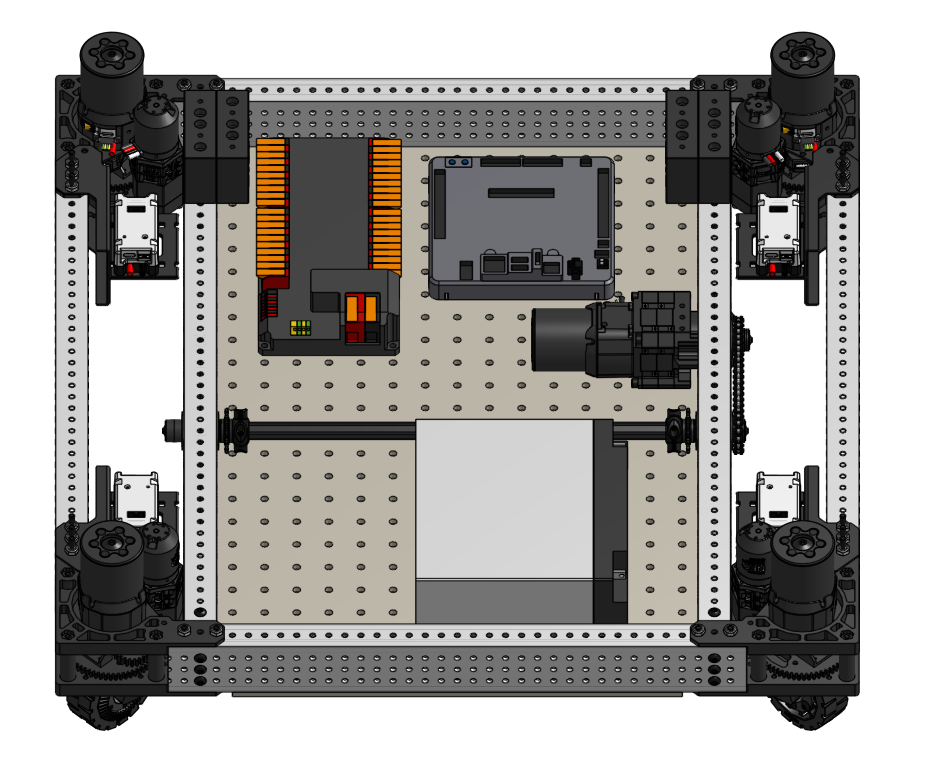
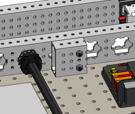
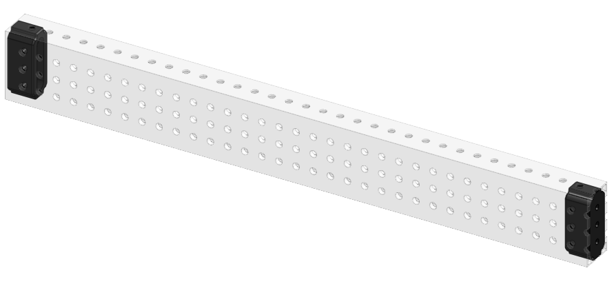
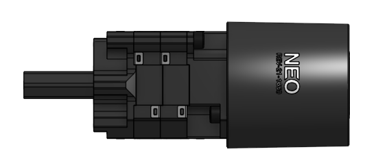
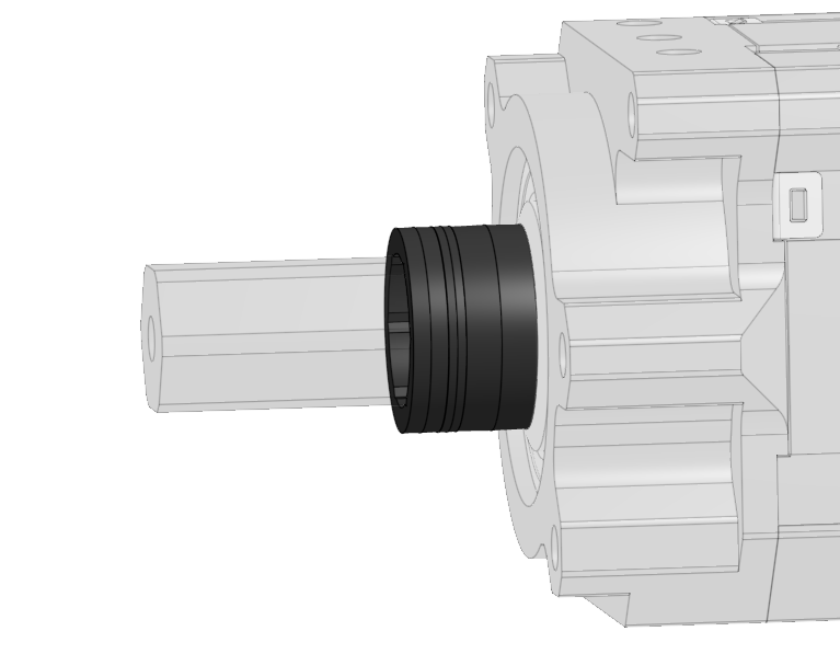
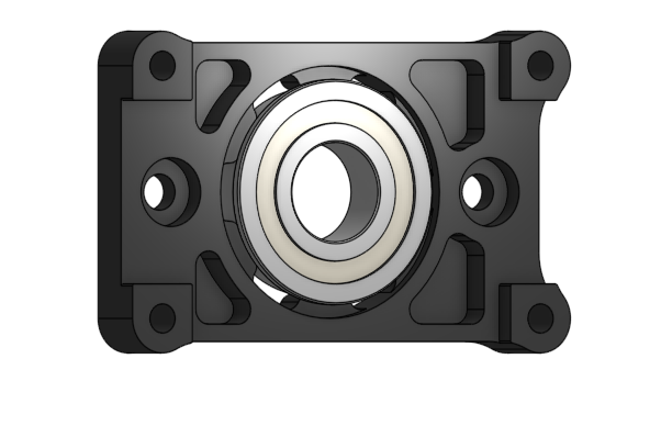
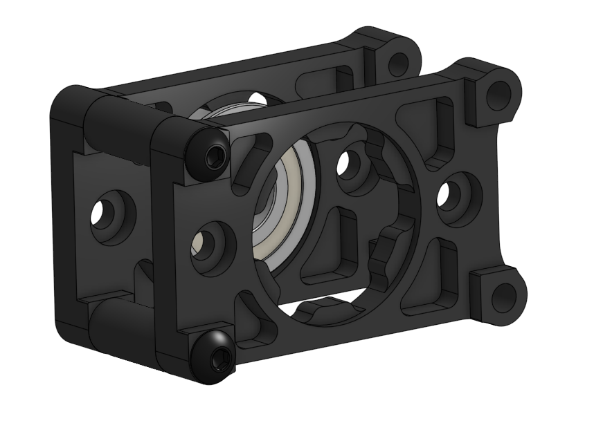
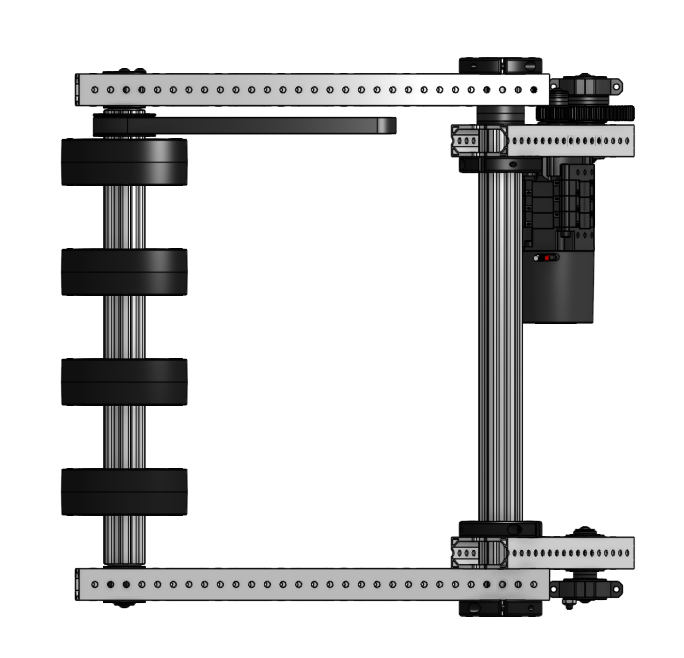
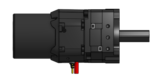
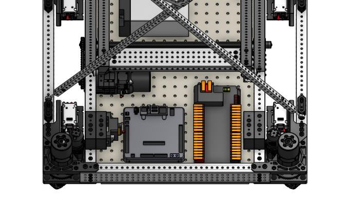
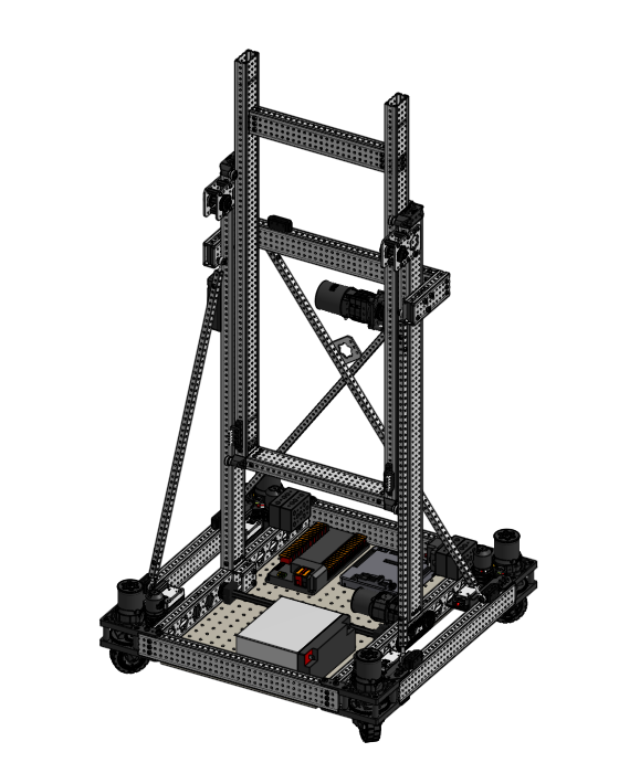
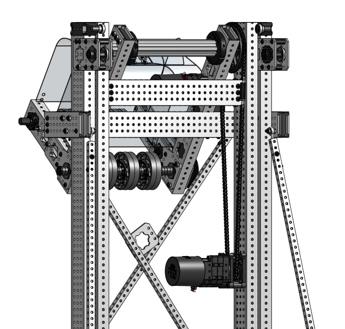
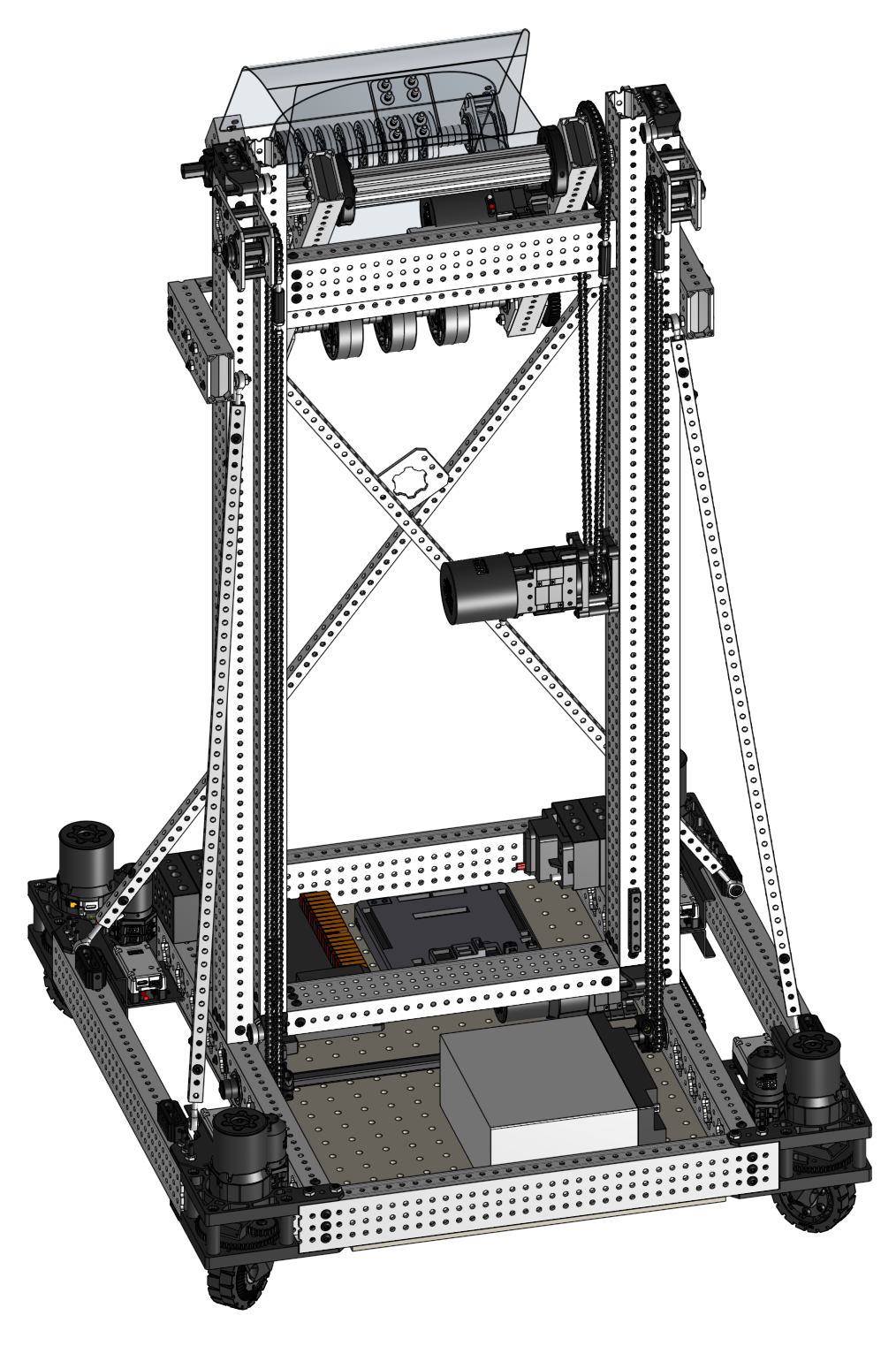
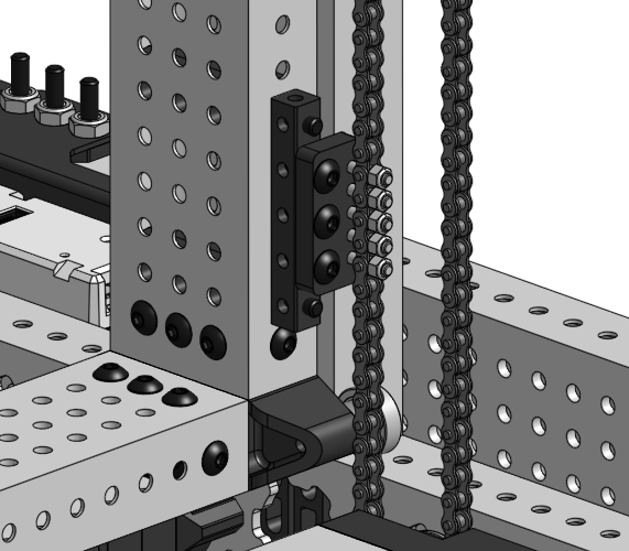
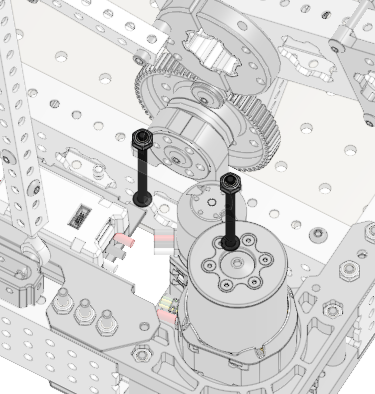
# 2025 REV ION Starter Bot Build Guide

## Quicklinks

<table data-header-hidden><thead><tr><th></th><th data-hidden></th><th data-hidden></th></tr></thead><tbody><tr><td><a href="#maxswerve-drivetrain">Drivetrain</a></td><td></td><td></td></tr><tr><td><a href="#maxlift-single-stage-elevator">MAXLift Single Stage Elevator</a></td><td></td><td></td></tr><tr><td><a href="#intake-arm-coral">Intake Arm (Coral)</a></td><td></td><td></td></tr><tr><td><a href="#algae-intake">Algae Intake</a></td><td></td><td></td></tr><tr><td><a href="https://store-t3eo8vwp22.mybigcommerce.com/content/docs/2025_REV_ION_FRC_Starter_Bot-BOM.pdf">Bill of Materials</a></td><td></td><td></td></tr><tr><td><a href="/pages/pWNzteR3xl3zJqYLZMRr">Cut List</a></td><td></td><td></td></tr></tbody></table>

## MAXSwerve Drivetrain

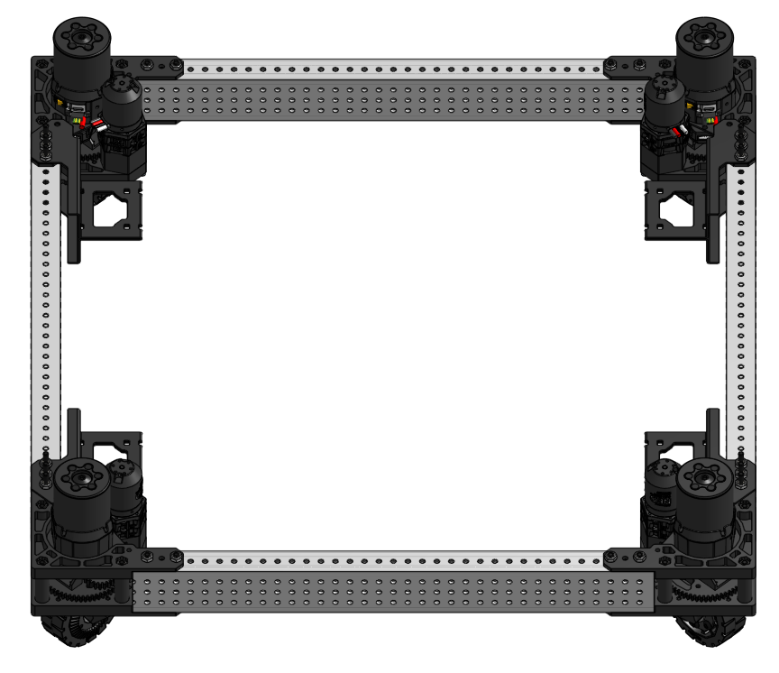
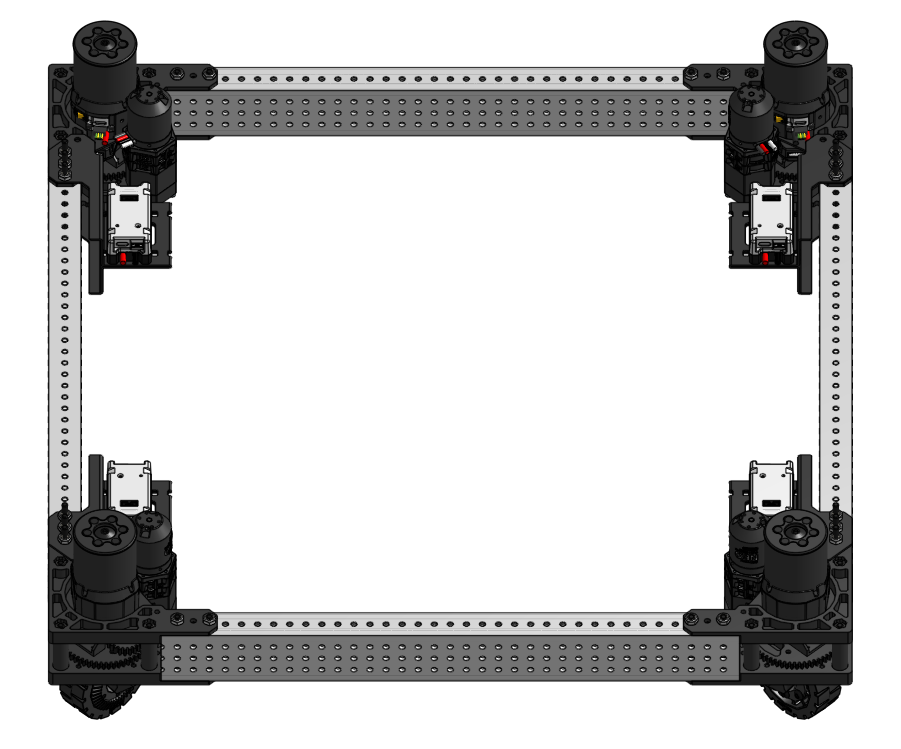
The 2025 REV ION Starter Bot drivetrain is designed with the MAXSwerve Module. Before you begin this section of the build guide you will need to [assemble four MAXSwerve Modules](https://docs.revrobotics.com/ion-build-system/build-guides/maxswerve-module-assembly).&#x20;

{% hint style="success" %}
For ease of wiring, we suggest building 2 modules with Left-Hand motor orientation and 2 modules with Right-Hand motor orientation.&#x20;
{% endhint %}

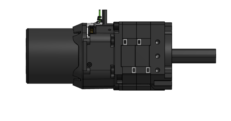
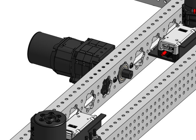
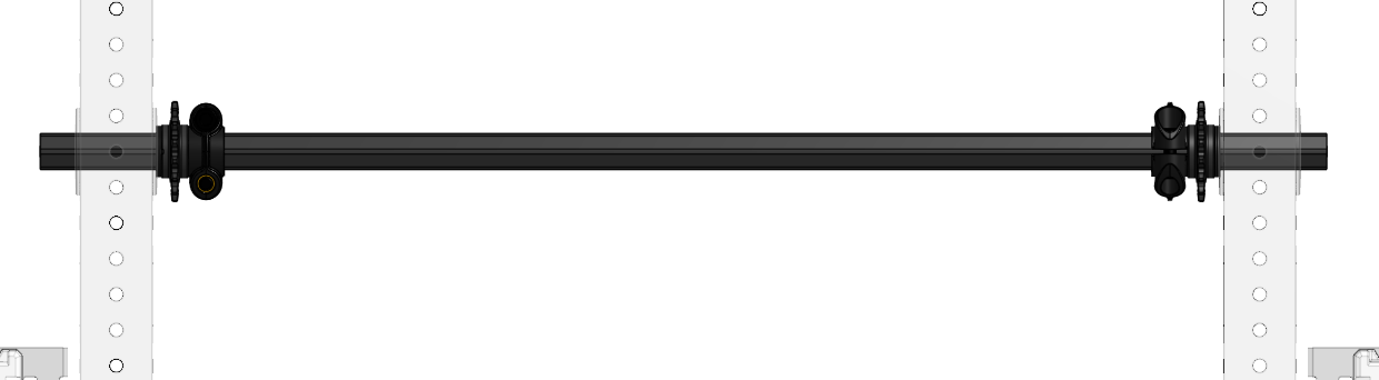
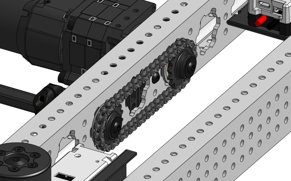
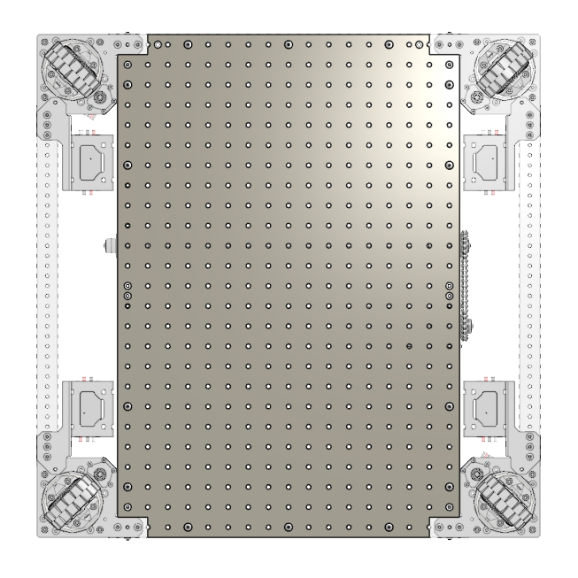
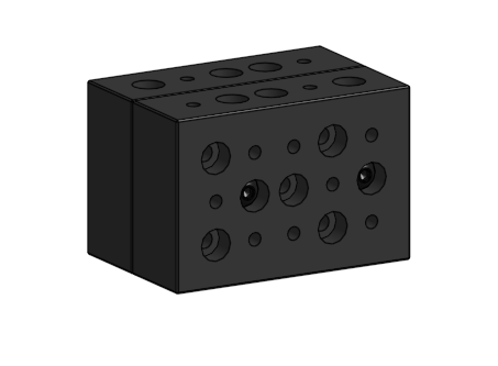
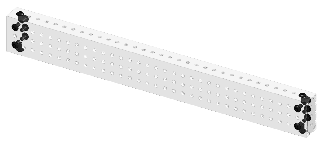
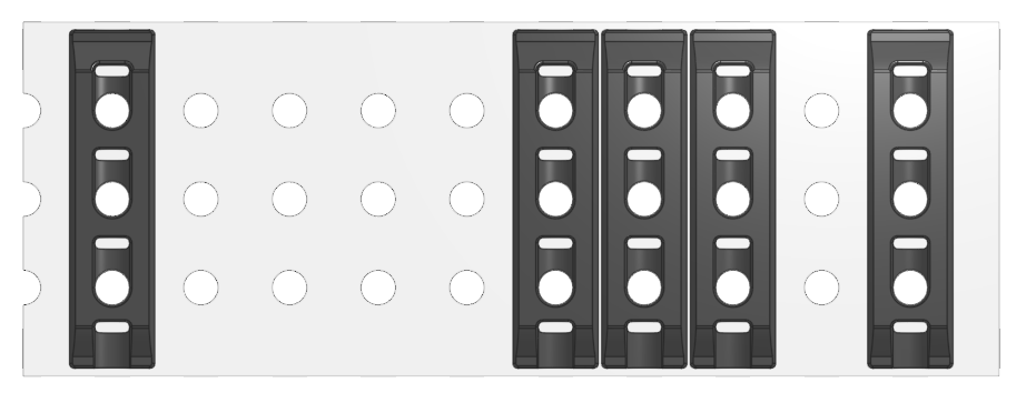
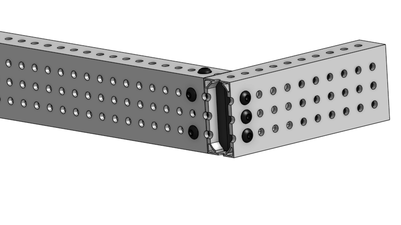
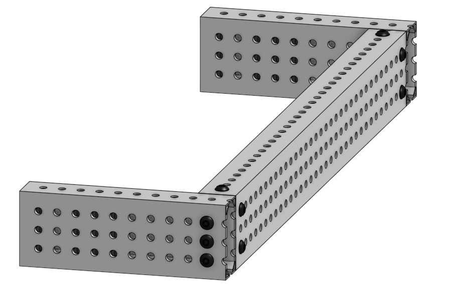
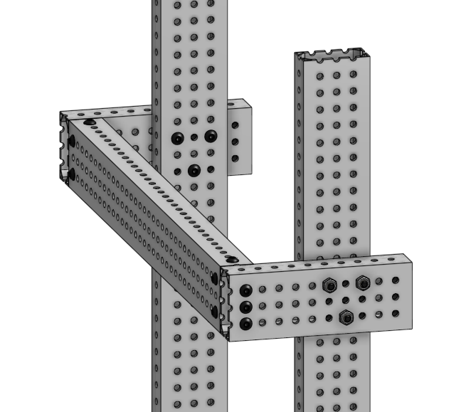
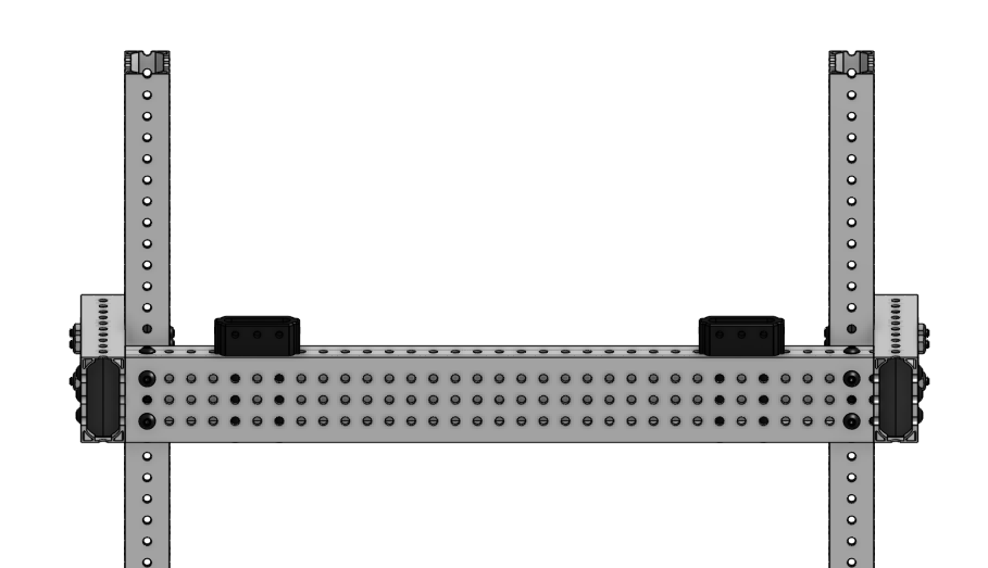
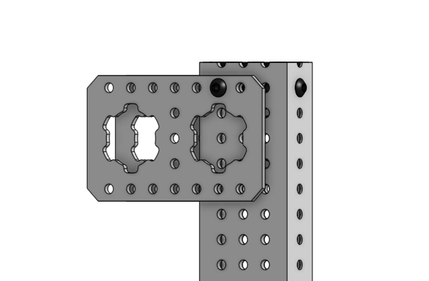
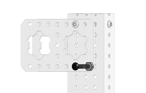
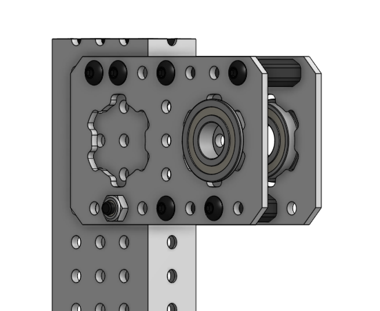
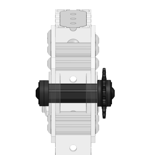
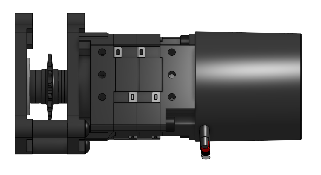
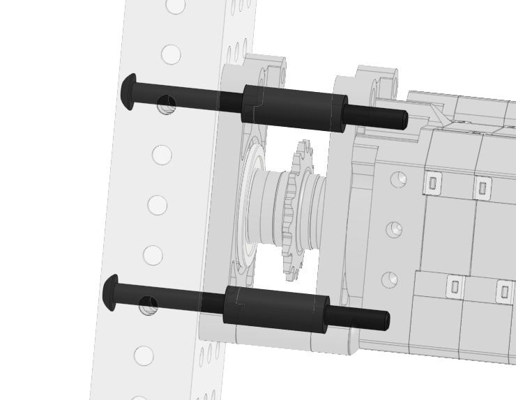
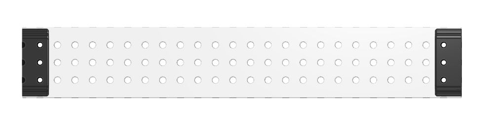
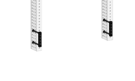
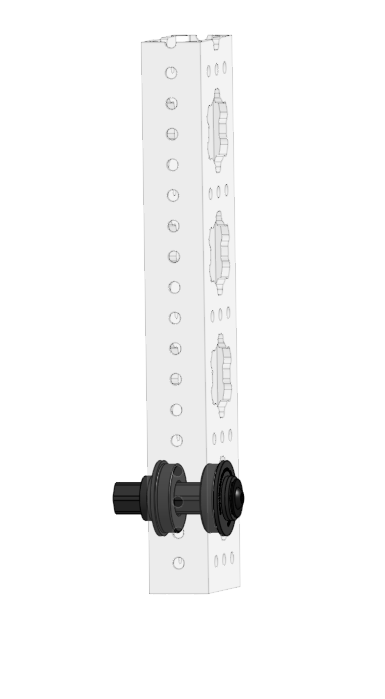
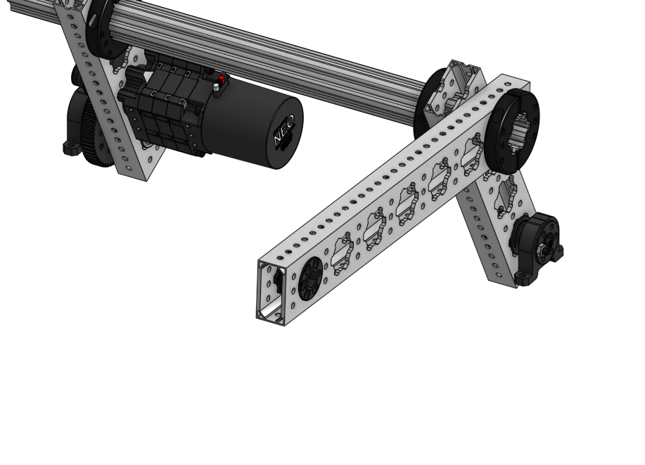
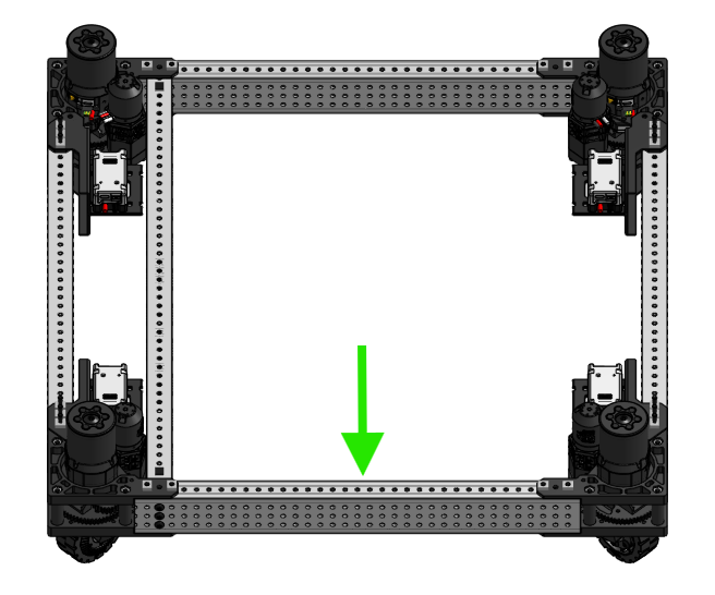
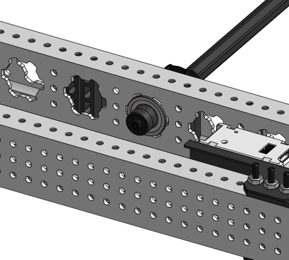
<table data-header-hidden><thead><tr><th>Step</th><th>Image</th><th data-hidden></th></tr></thead><tbody><tr><td><ol><li>Get:</li></ol><ul><li>24 - MAXTube Internal Support 2x1</li><li>4 - MAXTube 2x1 with Grid Pattern - cut to 18in</li></ul><p>Insert 3 MAXTube Internal Supports into each end of the MAXTube pieces. Take care to ensure they do not fall out before securing them in the next step.</p></td><td><img src="/files/ffjjwuoD31NY7IUoVbVt" alt="" data-size="original"></td><td></td></tr><tr><td><ol start="2"><li>Get:</li></ol><ul><li>4 - MAXSwerve Module, fully assembled</li><li>12 - #10-32 Button Head Screws x 3in</li><li>12 - #10-32 Low Profile Nylon Lock Nut</li><li>2 - Assemblies from Step #1</li></ul><p>Attach one MAXSwerve Module to each end of an 18in MAXTube piece. We recommend mounting one right-hand and one left-hand module so that the wires point toward each other. </p><p></p><p>Secure the MAXSwerve Modules to the MAXTube using screws so that each screw passes through a MAXTube Internal Support and the Nylon Lock Nt is on top. </p><p></p><p>Make two of these. </p></td><td><img src="/files/hcpMQkfrNdLLg1Vph5Nr" alt="" data-size="original"></td><td></td></tr><tr><td><ol start="3"><li>Get:</li></ol><ul><li>8 - #10-32 Button Head Screws x 3in</li><li>8 - #10-32 Low Profile Nylon Lock Nut</li><li>2 - Assemblies from Step #1</li></ul><p>Connect the two MAXSwerve Module rails with two screws on each side so that each screw passes through a MAXTube Internal Support and the Nylon Lock Nut is on top.<br><br><strong>Note - Leave the middle hole and MAXTube Internal Support empty, it will be used in a later step</strong></p></td><td><img src="/files/sRFwViVVsPebvtf5yG3x" alt="" data-size="original"></td><td></td></tr><tr><td><ol start="4"><li>Get:</li></ol><ul><li>4 - SPARK MAX Motor Controller</li><li>4 - Absolute Encoder Adapter</li><li>4 - JST PH 6-pin Extension Cable - 30cm</li><li>12 - WAGO 221 Inline Splicing Connector</li><li>Zip Ties</li></ul><p>For each MAXSwerve Module, wire the NEO 550 and Through Bore Encoder to a SPARK MAX with an Absolute Encoder Adapter installed in the data port. Then, secure the SPARK MAX to the module’s SPARK MAX Mounting Bracket using zip ties. </p><p><br><strong>Note - Placing a zip tie over the Absolute Encoder Adapter and aligned with its notches is highly recommended to ensure a secure connection</strong></p></td><td><img src="/files/6jDKNJpuNO3xmjllvaAz" alt="" data-size="original"></td><td></td></tr><tr><td><ol start="5"><li>Get:</li></ol><ul><li>5 - MAXTube Internal Support 2x1</li><li>1 - MAXTube with MAX Pattern cut to 23in </li></ul><p>Counting from the first hole on the factory edge of the 23in , insert 5 MAXTube Internal Supports so that they align with holes, 13, 17, 23, 24,and 25.<br><br><strong>Note: Please see our guide to</strong> <a href="/pages/pWNzteR3xl3zJqYLZMRr#staying-on-pitch"><strong>Staying on Pitch</strong></a> <strong>for tips on measuring for your cut</strong>s</p></td><td><img src="/files/5iqEXkmNUET9DVmlV2jH" alt="" data-size="original"></td><td></td></tr><tr><td><ol start="6"><li>Get:</li></ol><ul><li>2 - MAXTube Endcap - 2x1</li><li>4 - #10-32 Button Head Screws x 5/16in</li></ul><p>Insert MAXTube Endcaps into both ends of the MAXTube with MAXPattern. Secure both MAXTube Endcaps with 2 screws, onon the top and bottom of the 1in face of the MAXTube. </p></td><td><img src="/files/6cpgTFyRJkLpp5xEuwbK" alt="" data-size="original"></td><td></td></tr><tr><td><ol start="7"><li>Get:</li></ol><ul><li>6 - #10-32 Button Head Screws x 1 1/2in</li></ul><p>Add this MAXTube to your MAXSwerve Drivetrain as the first middle brace. The factory edge, used as a reference in the above steps, should be mounted towards the front of the robot indicated by the green arrow. </p></td><td><img src="/files/JjNoq023WsLxeaf0FyNJ" alt="" data-size="original"></td><td></td></tr><tr><td><ol start="8"><li>Get:</li></ol><ul><li>4 - MAXTube Internal Support 2x1</li><li>1 - MAXTube with MAX Pattern cut to 23in</li></ul><p>Counting from the first complete hole on the factory edge of the 35.5in , insert 4 MAXTube Internal Supports so that they align with holes 22, 23, 24, and 28</p><p><br><strong>Note: Please see our guide to</strong> <a href="/pages/pWNzteR3xl3zJqYLZMRr#staying-on-pitch"><strong>Staying on Pitch</strong></a> <strong>for tips on measuring for your cut</strong>s</p></td><td><img src="/files/sz2Bmox610AlvmKIrbxm" alt="" data-size="original"></td><td></td></tr><tr><td><ol start="9"><li>Get:</li></ol><ul><li>2 - MAXTube Endcap - 2x1</li><li>4 - #10-32 Button Head Screws x 5/16in</li></ul><p>Insert MAXTube Endcaps into both ends of the MAXTube with MAXPattern. Secure both MAXTube Endcaps with 2 screws, onon the top and bottom of the 1in face of the MAXTube.  </p></td><td><img src="/files/Q37nSPMrY5X5mYXOEx5w" alt="" data-size="original"></td><td></td></tr><tr><td><ol start="10"><li>Get:</li></ol><ul><li>6 - #10-32 Button Head Screws x 1 1/2in</li></ul><p>Add the MAXTube to your MAXSwerve Drivetrain as the second middle brace. The factory edge, used as a reference in the above steps, should be mounted towards the front of the robot indicated by the green arrow as shown. <br></p></td><td><img src="/files/rSPXVdDsQ6io8XCuugL8" alt="" data-size="original"></td><td></td></tr><tr><td><ol start="11"><li>Get:</li></ol><ul><li>2 - 1/2in Rounded Hex Bearing - Flanged - 1.125in OD</li></ul><p>Place one Flanged Bearing on either side of the right-side brace MAXTube in the 7th MAXSpline from the front of the robot.</p></td><td><img src="/files/yUOqvF9WIsyxsIlo1J39" alt="" data-size="original"></td><td></td></tr><tr><td><p></p><ol start="12"><li>Get:</li></ol><ul><li>1 - NEO Vortex Brushless Motor</li><li>1 - SPARK Flex Motor Controller, with docking hardware</li><li>1 - Vortex MAXPlanetary Input Kit</li><li>2 - #10-32 Socket Head Screws x 1/2in </li><li>2 - 5:1 MAXPlanetary Cartridge</li><li>1 - MAXPlanetary 1/2in Hex Socket Output </li><li>1 - 10-32 Button Head Screw 1/2in</li><li>1 - 1/2in Rounded Hex Shaft - 2.0in - Tapped</li><li>2 - #10-32 Socket Head Screws x 1-1/2in </li></ul><p>Assemble a 25:1 MAXPlanetary Gearbox with a 2.0in output shaft driven by a NEO Vortex<br></p></td><td><img src="/files/Z2Zu0lQQb6FPPeva1IFm" alt="" data-size="original"></td><td></td></tr><tr><td><ol start="13"><li>Get:</li></ol><ul><li>2 - #10-32 Button Head Screws x 1-1/2in</li></ul><p>Mount the MAXPlanetary Gearbox as shown, ensuring that the bearings stay in place.<br><br>Note: At this time consider which direction your SPARK Flex is facing and the rest of your robot’s wiring. For the 2025 Starter Bot, we chose to have the Status LED face towards the back of the robot.</p></td><td><img src="/files/wGFGKmbS2VUybnnFre1F" alt="" data-size="original"></td><td></td></tr><tr><td><ol start="14"><li>Get:</li></ol><ul><li>4 - 1/2in Rounded Hex Bearing - Flanged - 1.125in OD</li></ul><p>Place one Flanged Bearing on either side of both MAXTube bracing pieces in the 5th MAXSpline from the front of the robot. </p></td><td><img src="/files/zWPxJccidqTwcrCHLMkr" alt="" data-size="original"></td><td></td></tr><tr><td><ol start="15"><li>Get:</li></ol><ul><li>1 - 1/2in Rounded Hex Shaft cut to 18in</li><li>2 - 1/2in Hex Shaft Spacer - 1/16in</li><li>2 - #25 Hub Sprocket - 1/2in Hex - 16T</li><li>2 - 2 Piece 1/2" Hex Plastic Shaft Collar</li></ul><p>Insert the 1/2in Rounded Hex Shaft through one set of bearings and then add a 1/16 Spacer, 16T Sprocket, 1/2in Hex Shaft Collar, 1/2in Hex Shaft Collar, 16T Sprocket, and 1/16 Spacer to the hex shaft before exiting through the other set of bearings. </p><p></p><p><strong>Note: do not fully tighten the shaft collars at this time.</strong> </p></td><td><img src="/files/KHWLrqxVp7kNdWCodwZj" alt="" data-size="original"></td><td></td></tr><tr><td><ol start="16"><li>Get:</li></ol><ul><li>2 - #25 Hub Sprocket - 1/2in Hex - 16T </li><li>1 - 48 Link # 25 Chain Loop</li></ul><p>Connect the 1/2in Hex output from the MAXPlanetary Gearbox to the 18in Piece of 1/2in Rounded Hex Shaft with 16T sprockets and a 48 link chain loop.</p></td><td><img src="/files/PdpqIGyBFzsOOzpF9HYZ" alt="" data-size="original"></td><td></td></tr><tr><td><ol start="17"><li>Get:</li></ol><ul><li>1 - 1/2in Hex Shaft Spacer - 1/8in</li><li>2 - #10-32 Shaft End Screw</li></ul><p>Place the 1/8in Hex Shaft spacer on the output shaft of the MAXPlanetary Gearbox. Then, secure the Sprockets and chain to the 1/2in Rounded Hex Shaft with Shaft End Screws.</p></td><td><img src="/files/i5S7ql51gYoAFl9fOHYr" alt="" data-size="original"></td><td></td></tr><tr><td><ol start="18"><li>Get:</li></ol><ul><li>1 - 1/2in Hex Shaft Spacer - 1/2in</li><li>2 - #10-32 Shaft End Screw</li></ul><p>Secure the other side of the 18in long Rounded Hex Shaft with a 1/2in Hex Shaft Spacer and a Shaft End Screw. Then, </p><p><br></p></td><td><img src="/files/BLy0meVhaYnI2TDAojYa" alt="" data-size="original"></td><td></td></tr><tr><td><ol start="19"><li>Get:</li></ol><ul><li>Belly Pan Material - Cut to desired size</li><li>22 - 3/16in Rivets - 0.251-0.375in Grip Length</li></ul><p>Rivet the belly pan to the underside of the MAXSwerve Drivetrain as shown.</p></td><td><img src="/files/qsJlDVVW0wLaxLGjsqkj" alt="" data-size="original"></td><td></td></tr><tr><td><em><strong>Note: We recommend pausing here to mount your robot’s main electronics</strong>.</em></td><td><img src="/files/cE551Obj0gYg5HXaN1PH" alt="" data-size="original"></td><td></td></tr><tr><td><ol start="20"><li>Get: </li></ol><ul><li>4 - Ballast Block - 3in x 2in x 1in</li><li>4 - #10-32 Button Head Screws x 1-1/4in</li></ul><p>Connect 2 Ballast Blocks using 2 screws as shown.<br><br>Make 2 of these. </p></td><td><img src="/files/FFiMThjG7ELQHgR0XghV" alt="" data-size="original"></td><td></td></tr><tr><td><ol start="21"><li>Get:</li></ol><ul><li>4 - #10-32 Button Head Screws x 2-3/4in<br></li></ul><p>Mount both Ballast Block assemblies to the back of the robot with two 2.75in screws each as shown</p></td><td><img src="/files/uFvrzcuMZMJsyukjM2zU" alt="" data-size="original"></td><td></td></tr><tr><td><ol start="22"><li>Get:</li></ol><ul><li>1 - MAXTube - 2x1 with Grid Pattern cut to 2in</li><li>1 - MAXTube Internal Support 2x1</li></ul><p>Place one MAXTube Internal Support within the 2in Piece of MAXTube as shown.</p></td><td><img src="/files/amteZttYH1G0iBfZFkWd" alt="" data-size="original"><br><img src="/files/KbI9hOWchw3BQljVGAUR" alt=""></td><td></td></tr><tr><td><ol start="23"><li>Get:</li></ol><ul><li>2 - #10-32 Button Head Screws x 2-1/4in</li><li>2 - #10-32 Low Profile Nylon Lock Nut</li></ul><p>Mount the MAXTube piece to the left brace with screws and nuts.</p></td><td><img src="/files/Sl8Sr57ftPS99JE5zKdw" alt="" data-size="original"></td><td></td></tr><tr><td><ol start="24"><li>Get:</li></ol><ul><li>4 - MAXTube Endcap 2x1</li><li>8 - #10-32 Button Head Screws x 2-1/4in</li></ul><p>Attach one MAXTube Endcap to each corner of the Drivetrain as shown in the picture. <br></p><p><strong>Note: The top left MAXTube Endcap is not symmetrical with the others.</strong></p></td><td><img src="/files/8nxQi3NM6I6b5selpStb" alt="" data-size="original"></td><td></td></tr></tbody></table>
## MAXLift Single-Stage Elevator

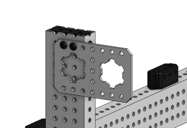
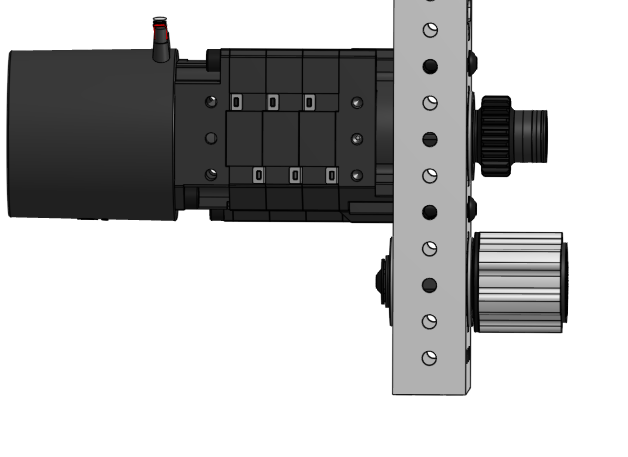
<table data-header-hidden><thead><tr><th></th><th></th><th data-hidden></th></tr></thead><tbody><tr><td><ol><li>Get:</li></ol><ul><li>1 -  MAXTube 2x1 with Grid Pattern - cut to 17in</li><li>2 - MAXTube Endcap 2x1</li></ul><p>. Insert one MAXTube endcap into each end of the 17in piece of MAXTube.</p></td><td><img src="/files/4lLDNX2O7peka2MRSYA7" alt="" data-size="original"></td><td></td></tr><tr><td><ol start="2"><li>Get:</li></ol><ul><li>14 - #10-32 Button Head Screws x 3/8in </li></ul><p>Secure both Endcaps with 7 screws each. Leave both middle spots open on one of the 2in sides of the MAXTube.</p><p><br></p></td><td><img src="/files/VM19n1ywsKfcmBxk1uY4" alt="" data-size="original"></td><td></td></tr><tr><td><ol start="3"><li>Get</li></ol><ul><li>1 - MAXTube 2x1 with Grid Pattern - cut to 5.5in 5 - MAXTube Internal Spacer 2x1 </li></ul><p>Add 5 MAXTube Internal Spacers to a 5.5in piece of MAXTube as shown in the image.</p></td><td><img src="/files/TD4Gf7tq6emfyH9E6Pwi" alt="" data-size="original"></td><td></td></tr><tr><td><ol start="4"><li>Get:</li></ol><ul><li>3 - #10-32 Button Head Screws x 1-1/2in<br></li></ul><p>Attach the 5.5in section of MAXTube to the right side of the 17in MAXTube piece using 3 Screws and the existing MAXTube Endcap. </p><p></p><p><strong>Note: The 17in MAXTube should be positioned so that the 2in side with only 4 screws showing is facing the builder.</strong></p></td><td><img src="/files/hfyfitZ5CGmQaccNugni" alt="" data-size="original"></td><td></td></tr><tr><td><ol start="5"><li>Get:</li></ol><ul><li>1 - MAXTube 2x1 with Grid Pattern - cut to 5.5in </li><li>5 - MAXTube Internal Spacer 2x1 </li></ul><p>Add 5 MAXTube Internal Spacers to a 5.5in piece of MAXTube as shown in the image.</p></td><td><img src="/files/3kxWYnoGVHcjsLq7I3Gn" alt="" data-size="original"></td><td></td></tr><tr><td><ol start="6"><li>Get:</li></ol><ul><li>3 - #10-32 Button Head Screws x 1-1/2in</li></ul><p> Attach the 5.5in section of MAXTube to the right side of the 17in MAXTube piece using 3 Screws and the existing MAXTube Endcap.</p></td><td><img src="/files/V1l31AXdCLJumiVahkao" alt="" data-size="original"></td><td></td></tr><tr><td><ol start="7"><li>Get:</li></ol><ul><li>1 - MAXTube 2x1 with - Light - Grid Pattern - cut to 35.5in </li><li>2 - MAXTube Internal Spacer - 2x1 Light </li></ul><p>Add two MAXTube Internal Spacers to the MAXTube, they should align with the 56th and 58th holes from the factory edge.</p></td><td><img src="/files/uG4lC9nAjmpLQAsvFuIj" alt="" data-size="original"></td><td></td></tr><tr><td><ol start="8"><li>Get:</li></ol><ul><li>3 - #10-32 Button Head Screws x 2-1/4in </li><li>3 - #10-32 Low Profile Nylon Lock Nut </li></ul><p>Connect the 35in piece of MAXTube to the existing assembly as shown using screws and nuts. The screws will pass through the MAXTube Internal Spacers from previous steps.</p></td><td><img src="/files/6MuYk8syRBg3vfOTiWaC" alt="" data-size="original"><br><img src="/files/wl6lH0elKRyBHV8vXU1A" alt=""></td><td></td></tr><tr><td><ol start="9"><li>Get:</li></ol><ul><li>Get: 1 - MAXTube 2x1 with - Light - Grid Pattern - cut to 35.5in </li><li>2 - MAXTube Internal Spacer - 2x1 Light </li></ul><p>Add two MAXTube Internal Spacers to the MAXTube, they should align with the 56th and 58th holes from the factory edge..</p></td><td><img src="/files/uHMUClrQLrijgXBImE6l" alt="" data-size="original"></td><td></td></tr><tr><td><p> 10. Get:</p><ul><li>3 - #10-32 Button Head Screws x 2-1/4in </li><li>3 - #10-32 Low Profile Nylon Lock Nut </li></ul><p>Connect the 35in piece of MAXTube to the existing assembly as shown using screws and nuts. The screws will pass through the MAXTube Internal Spacers from previous steps.</p></td><td><img src="/files/GK9s4bl9hSdMBfNApN31" alt="" data-size="original"><br><img src="/files/lkHzUqVnuekjAF7LfT0m" alt=""></td><td></td></tr><tr><td><ol start="11"><li>Get:</li></ol><ul><li>2 - MAXTube Endcap 2x1 4 - #10-32 Button Head Screws x 2-1/2in </li></ul><p>Attach 2 MAXTube Endcaps to the MAXTube support as shown. Use 2 screws for each MAXTube Endcap.</p></td><td><img src="/files/YOTApSPHXCGs40SFjhFe" alt="" data-size="original"></td><td></td></tr><tr><td><ol start="12"><li>Get:</li></ol><ul><li>2 - MAXTube Endcap 2x1 - Light </li><li>4 - #10-32 Button Head Screws x 3/8in </li></ul><p>Cap the ends of the 35.5in MAXtube Sections with MAXTube Endcaps. Secure each endcap with 2 screws, one on each 1in side of the MAXTube.</p></td><td><img src="/files/IloRnUR690jEAu9D7PvN" alt="" data-size="original"></td><td></td></tr><tr><td><ol start="13"><li>Get:</li></ol><ul><li>1 - MAXSpline Bracket - Stacked </li><li>2 - #10-32 Button Head Screws x 5/16in </li></ul><p>Mount the MAXSpline Bracket to the MAXTube as shown with Screws.</p></td><td><img src="/files/udJ7SAPv0K1KwmMfdETY" alt="" data-size="original"></td><td></td></tr><tr><td><ol start="14"><li>Get:</li></ol><ul><li>1 - MAXSpline Bracket - Stacked </li><li>1 - #10-32 Button Head Screws x 5/16in </li></ul><p>Add a second MAXSpline Bracket to the opposite of the MAXTube.</p></td><td><img src="/files/0Cd0myoGNQWJmEWiCxOo" alt="" data-size="original"></td><td></td></tr><tr><td><ol start="15"><li>Get:</li></ol><ul><li>1 - #10-32 Button Head Screws x 1-1/2in </li><li>1 - #10-32 Low Profile Nylon Lock Nut </li></ul><p>Secure the two MAXSpline Brackets to the MAXTube with a screw and nylon lock nut.</p></td><td><img src="/files/1AS9mI5R8AAGy993IgaD" alt="" data-size="original"></td><td></td></tr><tr><td><ol start="16"><li>Get:</li></ol><ul><li>4 - #10 Standoff - 1.00in </li><li>8 - #10-32 Button Head Screws x 1/2in </li></ul><p>Add 4 #10 standoffs between the MAXSpline Brackets using screws to secure in place.</p></td><td><img src="/files/9on0nPq5bFGeod7DJrWs" alt="" data-size="original"></td><td></td></tr><tr><td><ol start="17"><li>Get:</li></ol><ul><li>2 - 1/2in Rounded Hex Bearing - Flanged - 1.125in OD </li></ul><p>Add a 1/2in Rounded Hex Bearing in each of the MAXSpline Brackets. The flange of the bearing should be on the outside of the brackets.</p></td><td><img src="/files/cSvGJ94amA9ANDyJwNDY" alt="" data-size="original"></td><td></td></tr><tr><td><ol start="18"><li>Get:</li></ol><ul><li>1 - 1/2in Rounded Hex Shaft - 2.0in - Tapped </li><li>1 - 1/2in Hex Shaft Spacer - 1/4in </li><li>1 - #25 Hub Sprocket - 1/2in Hex - 16T </li><li>2 - #10-32 Shaft End Screw </li></ul><p>Insert a Shaft End Screw on one side of a 2in long piece of 1/2in Rounded Hex Shaft, and then slide on a 1/4in spacer. Pass this assembly through the bearings so that the spacer is on the outside of the assembly. To secure the hex shaft in place, add the 16T Sprocket and then install another shaft end screw.</p></td><td><img src="/files/FVGZ9naOCe8YsUL2KLgZ" alt="" data-size="original"></td><td></td></tr><tr><td><ol start="19"><li>Get:</li></ol><ul><li>1 - MAXSpline Bracket - Stacked </li><li>2 - #10-32 Button Head Screws x 5/16in </li></ul><p>Mount the MAXSpline Bracket to the MAXTube as shown with Screws.</p></td><td><img src="/files/K5sNPrbH7WtgOZQxbVSg" alt="" data-size="original"></td><td></td></tr><tr><td><ol start="20"><li>Get:</li></ol><ul><li>1 - MAXSpline Bracket - Stacked </li><li>1 - #10-32 Button Head Screws x 5/16in </li></ul><p>Add a second MAXSpline Bracket to the opposite of the MAXTube.</p></td><td><img src="/files/BMVjIT1o5NAt0FE8Qg2I" alt="" data-size="original"></td><td></td></tr><tr><td><ol start="21"><li>Get:</li></ol><ul><li>1 - #10-32 Button Head Screws x 1-1/2in </li><li>1 - #10-32 Low Profile Nylon Lock Nut </li></ul><p>Secure the two MAXSpline Brackets to the MAXTube with a screw and nylon lock nut.</p></td><td><img src="/files/kc1rQh3oNXywxPlqqXmv" alt="" data-size="original"></td><td></td></tr><tr><td><ol start="22"><li>Get:</li></ol><ul><li>4 - #10 Standoff - 1.00in </li><li>8 - #10-32 Button Head Screws x 1/2in </li></ul><p>Add 4 #10 standoffs between the MAXSpline Brackets using screws to secure in place.</p></td><td><img src="/files/uVYgYf3MJIIdVat6lVjq" alt="" data-size="original"></td><td></td></tr><tr><td><ol start="23"><li>Get:</li></ol><ul><li>2 - 1/2in Rounded Hex Bearing - Flanged - 1.125in OD </li></ul><p>Add a 1/2in Rounded Hex Bearing in each of the MAXSpline Brackets. The flange of the bearing should be on the outside of the brackets.</p></td><td><img src="/files/1DJrQRZiccUJFFAYbDL6" alt="" data-size="original"></td><td></td></tr><tr><td><ol start="24"><li>Get:</li></ol><ul><li>1 - 1/2in Rounded Hex Shaft - 2.0in - Tapped </li><li>1 - 1/2in Hex Shaft Spacer - 1/4in </li><li>1 - #25 Hub Sprocket - 1/2in Hex - 16T </li><li>2 - #10-32 Shaft End Screw </li></ul><p>Insert a Shaft End Screw on one side of a 2in long piece of 1/2in Rounded Hex Shaft, and then slide on a 1/4in spacer. Pass this assembly through the bearings so that the spacer is on the outside of the assembly. To secure the hex shaft in place, add the 16T Sprocket and then install another shaft end screw.</p></td><td><img src="/files/ReFzpYg2ggx6kfZGv1kO" alt="" data-size="original"></td><td></td></tr><tr><td><ol start="25"><li>Get:</li></ol><ul><li>8 - #10-32 Button Head Screws x 1/2in </li><li>2 - MAXLift End-mount Bearing Block </li></ul><p>Mount two MAXLift Bearing Blocks to the top of the assembly using three screws each. The bearings should be facing the inside of the lift.<br><br>Set aside</p></td><td><img src="/files/710juJjPeCsaSAn5wCVC" alt="" data-size="original"></td><td></td></tr><tr><td><ol start="26"><li>Get:</li></ol><ul><li>1 - NEO V1.1 Brushless Motor </li><li>1 - MAXPlanetary Base Kit </li><li>2 - #10-32 Socket Head Screws x 1/2in </li><li>2 - 5:1 MAXPlanetary Cartridge </li><li>1 - 4:1 MAXPlanetary Cartridge</li><li>1 - 10-32 Button Head Screw 1/2in </li><li>1 - 1/2in Rounded Hex Shaft - 1.75in - Tapped </li><li>2 - #10-32 Socket Head Screws x 1-1/2in </li></ul><p></p><p>Assemble a 20:1 MAXPlanetary Gearbox with a 1.75in output shaft driven by a NEO V1.1 Motor.</p></td><td> <img src="/files/WzVLnx2niGUYveOy8XNM" alt=""></td><td></td></tr><tr><td><ol start="27"><li>Get:</li></ol><ul><li>1 - 1/2in Hex Shaft Spacer - 1/4in </li><li>1 - 1/2in Hex Shaft Spacer - 1/16in </li><li>1 - 1/2in Hex Shaft Spacer - 1/8in </li></ul><p>Add three spacers to the MAXPlanetary Gearbox’s output. </p><p></p><p>Set this aside, we recommend standing the assembly up on the back end of the motor.</p></td><td><img src="/files/IMVomf46JbKuQuR4CHb0" alt="" data-size="original"></td><td></td></tr><tr><td><ol start="28"><li>Get:</li></ol><ul><li>1 - MAXSpline 2x1 Bearing Blocks - Threaded Plate </li><li>1 - 1/2in Rounded Hex Bearing - Flanged - 1.125in OD </li></ul><p>Insert a bearing into the MAXSpline Bore of the Threaded Plate from one MAXSpline 2x1 Bearing Block pack. The flange of the bearing will sit in the recessed portion of the plate.</p></td><td><img src="/files/818NP13Z0jHy0iQW4JJk" alt="" data-size="original"></td><td></td></tr><tr><td><ol start="29"><li>Get:</li></ol><ul><li>1 - MAXSpline 2x1 Bearing Blocks - Clearance Plate </li><li>2 - #10-32 Button Head Screws x 1-1/2in </li><li>2 - #10 Spacer - 3/4in </li></ul><p>Use screws to attach the Clearance Plate to the Threaded Plate with two 3/4in #10 spacers between them. Both screws should be on the same short edge of the MAXSpline Bearing Block</p></td><td><img src="/files/lNWljwOYiiY2CtpMXj1s" alt="" data-size="original"></td><td></td></tr><tr><td><ol start="30"><li>Get:</li></ol><ul><li>1 - 1/2in Hex Shaft Spacer - 1/4in </li><li>1 - #25 Hub Sprocket - 1/2in Hex - 16T </li><li>1 - 20:1 MAXPlanetary Gearbox </li></ul><p>Assembly from Step 27 Carefully add the 20:1 MAXPlanetary Gearbox to the MAXSpline Bearing Block assembly. As you pass the output through, add a 16T Sprocket and a 1/4in spacer before the hex shaft reaches the bearing. </p><p></p><p>Set this aside, we recommend standing the assembly up on the back end of the motor.</p></td><td><img src="/files/i8nGvCgArPgYafvsPRc4" alt="" data-size="original"></td><td></td></tr><tr><td><ol start="31"><li>Get:</li></ol><ul><li>1 - MAXTube 2x1 - Light with Grid Pattern - cut to 35.5in </li><li>8 - MAXTube Internal Spacer - 2x1 Light </li></ul><p>Add two MAXTube Internal Spacers to the MAXTube, they should align with the 2nd, 6th, 30th, 34th, 59th, 60th,61st, and 67th holes from the factory edge.</p></td><td><img src="/files/Eknjqm3x1vHdkdRekISm" alt="" data-size="original"></td><td></td></tr><tr><td><ol start="32"><li>Get:</li></ol><ul><li>2 - #10-32 Button Head Screws x 2-3/4in </li><li>2 - #10 Spacer - 3/4in </li><li>MAXSpline Bearing Block +MAXPlanetary Gearbox Assembly </li></ul><p>Attach the MAXSpline Bearing Block assembly to the MAXTube using the spacers and screws. The screws will pass through the MAXTube internal spacers in the 30th and 24th holes, as well as both bearing block plates and the #10 spacers between them before threading into the MAXPlanetary Gearbox’s output.</p></td><td><img src="/files/kH0DCFWYeic1u1di7TUu" alt=""><br><img src="/files/XOKZVWphnevKWiuU8Cml" alt=""></td><td></td></tr><tr><td><ol start="33"><li>Get:</li></ol><ul><li>1 - MAXTube 2x1 - Light with Grid Pattern - cut to 12.5in </li><li>2 - MAXTube Endcap 2x1 Light</li></ul><p>Insert one MAXTube endcap into each end of the 12.5in piece of MAXTube.</p></td><td><img src="/files/mHuK5tFdqjnzlCnRlw5x" alt="" data-size="original"></td><td></td></tr><tr><td><ol start="34"><li>Get:</li></ol><ul><li>16 - #10-32 Button Head Screws x 3/8in </li></ul><p>Secure both endcaps with 8 screws each. </p></td><td><img src="/files/q8HBQa73cfe4vfTOK3RU" alt="" data-size="original"></td><td></td></tr><tr><td><ol start="35"><li>Get:</li></ol><ul><li>3- #10-32 Button Head Screws x 1-1/2in </li></ul><p>Attach the shorter section of MAXTube to the 35.5in long section using screws through the 59th, 60th, and 61st holes from the factory edge.</p><p></p><p>Ensure that the screws pass through the MAXTube Internal Supports properly.</p></td><td><img src="/files/vPaKL1NnPXAoHe8FNTI1" alt="" data-size="original"></td><td></td></tr><tr><td><ol start="36"><li>Get:</li></ol><ul><li>1 - MAXTube 2x1 - Light with Grid Pattern - cut to 35.5in </li><li>6 - MAXTube Internal Spacer - 2x1 Light </li></ul><p>Add two MAXTube Internal Spacers to the MAXTube, they should align with the 2nd, 6th, 59th, 60th, 61st, and 67th holes from the factory edge.</p></td><td><img src="/files/oZubvuxcacyXIMqcJdJV" alt="" data-size="original"></td><td></td></tr><tr><td><ol start="37"><li>Get:</li></ol><ul><li>3- #10-32 Button Head Screws x 1-1/2in </li></ul><p>Attach the 35.5in long MAXTube piece to the rest of the assembly using screws through the 59th, 60th, and 61st holes from the factory edge. </p><p></p><p>Ensure that the screws pass through the MAXTube Internal Supports properly.</p></td><td><img src="/files/HkCTuuIjLQqK5hUMIQcD" alt="" data-size="original"></td><td></td></tr><tr><td><ol start="38"><li>Get:</li></ol><ul><li>2 - 3/8in Nut Strip - 5pos </li><li>3- #10-32 Button Head Screws x 1-1/2in </li></ul><p>Add one nut strip to each leg of the assembly that has just been finished. Position them one hole away from the factory edge on the 1in face where the left leg is empty. </p><p></p><p><strong>Note: The screws will pass through the MAXTube Internal Supports</strong></p></td><td><img src="/files/r2LIUs6N8OUhG6aEoneb" alt="" data-size="original"></td><td></td></tr><tr><td><ol start="39"><li>Get:</li></ol><ul><li>1 - MAXTube 2x1 with Grid Pattern - cut to 12.5in </li><li>2 - MAXTube Endcap 2x1 </li><li>16 - #10-32 Button Head Screws x 3/8in </li></ul><p>Insert one MAXTube endcap into each end of the 12.5in piece of MAXTube and secure with screws.</p></td><td><img src="/files/qKVdsfxzoWUByIEKyRyf" alt="" data-size="original"></td><td></td></tr><tr><td><ol start="40"><li>Get:</li></ol><ul><li>8 - #10-32 Button Head Screws x 1/2in </li><li>2 - MAXLift End-Mount Bearing Block</li></ul><p>Mount two MAXLift Bearing Blocks to the MAXTube as shown using three screws each. The bearings will be facing away from the MAXTube.</p></td><td><img src="/files/U3xBnrX18ojn1fynOdXk" alt="" data-size="original"><br><img src="/files/NH0xPTqiCFhM88bOboGd" alt=""></td><td></td></tr><tr><td><ol start="41"><li>Get:</li></ol><ul><li>6 - #10-32 Button Head Screws x 1/2in </li></ul><p>Attach the 12.5in cross bar to the legs of the MAXLift last used in step 38 using 3 screws each.</p></td><td><img src="/files/IvqZ4btlxKqD4SDssADv" alt="" data-size="original"></td><td></td></tr><tr><td><ol start="42"><li>Get:</li></ol><ul><li>2 - MAXLift End-Mount Bearing Block - rollers </li></ul><p>If the rollers are not attached to your MAXLift Endmount Bearing Blocks, attach them now.</p></td><td><img src="/files/eGsBgH2Lxeft6IawLNeR" alt="" data-size="original"></td><td></td></tr><tr><td><ol start="43"><li>Get:</li></ol><ul><li>Both Assemblies (Static Stage and Single Stage) </li></ul><p>Slide the Single Stage, the smaller stage, into the Static Stage, the bigger stage. </p><p></p><p><strong>Note: Ensure that the MAXLift Bearing Blocks allow for smooth rolling during this step!</strong></p></td><td><img src="/files/3N0H1ILhUc9Ry5KQiNPG" alt="" data-size="original"></td><td></td></tr><tr><td><ol start="44"><li>Get:</li></ol><ul><li>4 - 1/2in by 1/2in MAXTube - Cut to 26.5in </li><li>4 - 3/8in Nut Strip - 5pos </li></ul><p>Insert one nut strip into each end of the MAXTube. Secure through the 3rd and 5th holes from the edge with screws at a perpendicular angle relative to each other.<br></p><p>Make two of these.</p></td><td><img src="/files/6V4WiXeEIVIlXKh0VNPh" alt="" data-size="original"></td><td></td></tr><tr><td><ol start="45"><li>Get:</li></ol><ul><li>4 - #10-32 Ball Joint Rod End - Right-hand Threaded </li></ul><p>Twist in one Ball Joint Rod End to each nut strip. At this time, screw them in all the way and hand tight so that they can be adjusted for length later.</p></td><td><img src="/files/McaWI61oOHTqRSwFLAYj" alt="" data-size="original"></td><td></td></tr><tr><td><ol start="46"><li>Get:</li></ol><ul><li>1 - #10-32 Button Head Screws x 1-1/2in </li><li>2 - #10-32 Low Profile Nylon Lock Nut </li></ul><p>Attach the 26.5in support rod to the 2x1 MAXTube as shown by passing a 1-3/4in Screw through the MAXTube with Internal Support and adding a nylon lock nut tightened to be flush with the 2x1 MAXTube. Then add the ball joint rod end and one more nylon lock nut to secure the support.</p></td><td><img src="/files/ey94yMtu9BiXdsTv3CX0" alt="" data-size="original"></td><td></td></tr><tr><td><ol start="47"><li>Get:</li></ol><ul><li>1 - #10-32 Button Head Screws x 1-1/2in </li><li>2 - #10-32 Low Profile Nylon Lock Nut </li></ul><p>Repeat the previous steps on the other side of the MAXLift with the 2nd support rod.</p></td><td><img src="/files/bcqir6iGr1eWl6R46eSO" alt="" data-size="original"></td><td></td></tr><tr><td><ol start="48"><li>Get:</li></ol><ul><li>4 - 1/2in by 1/2in MAXTube - Cut to 32.5in </li><li>4 - 3/8in Nut Strip - 5pos </li><li>4 - #10-32 Ball Joint Rod End - Right-hand Threaded </li></ul><p>Insert one nut strip into each end of the MAXTube. Secure in the 3rd and 5th holes from the edge with screws at a perpendicular angle relative to each other. Then, twist in one ball joint rod end to each nut strip. At this time, screw them in all the way and hand tight so that they can be adjusted for length later. </p><p></p><p>Make two of these.</p></td><td><img src="/files/DbQzwfMfZd7QZxE9dAGS" alt="" data-size="original"></td><td></td></tr><tr><td><p></p><ol start="49"><li>Get:</li></ol><ul><li>2 - #10-32 Button Head Screws x 3/4in </li><li>2 - #10 Spacer - 1/8in </li></ul><p>Attach the 32.5in support rods as shown to the MAXLift. Place one 1/8in spacer between the ball joint end rod and the MAXTube for both supports. </p></td><td><img src="/files/V5gN1Uheh5pHhExrNkVY" alt="" data-size="original"></td><td></td></tr></tbody></table>

## Intake Arm (Coral)

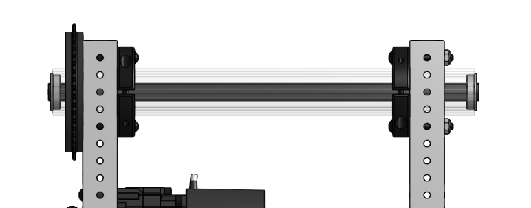
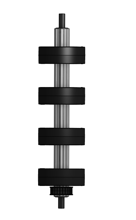
<table data-header-hidden><thead><tr><th></th><th></th><th data-hidden></th></tr></thead><tbody><tr><td><ol><li>Get:</li></ol><ul><li>2 - MAXTube Internal Support 2x1</li><li>1 - MAXTube 2x1 with Grid Pattern - cut to 15in</li></ul><p>Insert two MAXTube Internal Supports into the MAXTube as shown. </p></td><td><img src="/files/6ms5ijNCXkquCxziFii2" alt="" data-size="original"></td><td></td></tr><tr><td><ol start="2"><li>Get:</li></ol><ul><li>1 - 15in MAXTube from last step  </li><li>2 -MAXSpline Bracket - MAX Pattern T</li><li>2 - #10-32 Button Head x 1-1/2in screws</li><li>2 - #10-32 Low Profile Nylon Lock Nut</li></ul><p>Attach two MAXspline brackets to 15in MAXTube as shown.</p></td><td><img src="/files/k7Gjd24dYMdW55MjjNAs" alt="" data-size="original"></td><td></td></tr><tr><td><ol start="3"><li>Get:</li></ol><ul><li>1 - 7in MAXTube 2x1 with MAX Pattern  </li><li>3 - #10-32 Button Head x 1-1/2in screws</li><li>3 - #10-32 Low Profile Nylon Lock Nut</li></ul><p>Attach the 7in MAXTube as shown.</p></td><td><img src="/files/UgdHAfC1aemdOqgVw1HV" alt="" data-size="original"></td><td></td></tr><tr><td><ol start="4"><li>Get:</li></ol><ul><li>1 - MAXTube 2x1 with Grid Pattern - cut to 15in</li><li>2 - MAXTube Internal Support 2x1</li><li>2 - RT25 Pulley - 1/2in Hex - 16T</li><li>1 - RT25 Belt - 1/2in Width - 80T</li></ul><p>Insert the two MAXTube internal supports as shown. Slide the two pulleys with the belt into the MAXTube. Take care to ensure they do not fall out before securing them in future steps. <br><br></p></td><td><img src="/files/mHRM431cD0OiXO9GJ2nX" alt="" data-size="original"></td><td></td></tr><tr><td><p></p><ol start="5"><li>Get:</li></ol><ul><li>1 - 15in MAXTube 2x1 with MAX Pattern  </li><li>2 -MAXSpline Bracket - MAX Pattern T</li><li>2 - #10-32 Button Head x 1-1/2in screws</li><li>2 - #10-32 Low Profile Nylon Lock Nut</li></ul><p>Attach two MAXspline brackets to 15in MAXTube as shown, the belt should go around the left screw. </p></td><td><img src="/files/ZihLySEbLKXotLyzR3Pm" alt="" data-size="original"></td><td></td></tr><tr><td><ol start="6"><li>Get:</li></ol><ul><li>2 - MAX Pattern Plates - 3 Pos</li><li>4 - #10-32 Button Head x 3/8in screws</li><li>2 - #10 Standoff - 3/4in</li></ul><p>Attach the plates as shown.</p></td><td><img src="/files/fmcVfLGfhzdS5dQoikHB" alt="" data-size="original"></td><td></td></tr><tr><td><ol start="7"><li>Get:</li></ol><ul><li>2 - RT25 Pulley - 1/2in Hex - 16T</li><li>1 - RT25 Belt - 1/2in Width - 48T</li><li>4 - #10 Standoff - 3/4in</li><li>8 - #10-32 Button Head x 3/8in screws</li></ul><p>Wrap the belt around both pulleys, then install four standoffs as shown. Take care to ensure they do not fall out before securing them in future steps. </p></td><td><img src="/files/iXI8m5p9axxSx0mbSBDl" alt="" data-size="original"></td><td></td></tr><tr><td><ol start="8"><li>Get:</li></ol><ul><li>2 - MAXSpline Spacer - 1/8in</li><li>6 - Flanged Bearing for 1/2in Rounded Hex</li><li>2 - 1/2in Rounded Hex Shaft - 12in tapped</li><li>1 - 1/2in Rounded Hex Shaft - 2in tapped</li><li>2 - Shaft End Screws</li></ul><p>Insert six bearings into the MAX plates and MAXTube, with MAXSpline spacers behind the bearings in the MAXPlates as shown. Slide the hex shafts into the bearings, with the 2in shaft in the middle bearings as shown. Secure the top shaft with a shaft end cap screw then ass a end shaft screw on the inside of the 2in hex shaft.</p></td><td><img src="/files/E4ywxit8k7uASzyeiJbi" alt="" data-size="original"></td><td></td></tr><tr><td><ol start="9"><li>Get: </li></ol><ul><li>3 - MAXHub - 1/2in Hex - Plastic</li><li>3 - 3in - MAXSpline - Medium (Dark Gray) - Compliant Wheel</li><li>6 - #10-32 Socket Head Screw x 3/4in</li></ul><p>Insert two MAXHubs into a compliant wheel and secure the hubs with two socket head screws. Assemble three of these wheels with hubs. </p></td><td><img src="/files/2a8EvZjmKuXO9F19T30m" alt="" data-size="original"></td><td></td></tr><tr><td><ol start="10"><li>Get:</li></ol><ul><li>4 - 1/2in Hex Spacers - 1/2in</li><li>9 - 1/2in Hex Spacers - 1/4in</li><li>8 - 2in - 1/2in Hex - Medium (Dark Gray) - Compliant Wheels</li><li>3 - 3in Compliant Wheels from the previous step</li><li>2 - 20DP Gear - 1/2in Hex - 50T</li><li>2 - Shaft End Screws</li></ul><p>On the top shaft slide on two 1/2in hex shaft spacers, then slide on an alternating 1/4in spacer and compliant wheel until you have eight wheels and nine 1/4in spacers, then add two more 1/2in spacers.<br><br>On the middle shaft slide on the 50T gear and a 1/8in spacer then a shaft end screw. <br><br>On the left side of the bottom shaft, slide on a 50t gear and a shaft end screw. On the right side slide on three 1/2in hex spacers, a 1/8in spacer, then alternate a 3in compliant wheel with two 1/2in spacers ending with an additional 1/2in spacer as shown.</p></td><td><img src="/files/vuaQNoebY5mH7NZCe7Iw" alt="" data-size="original"></td><td></td></tr><tr><td><p></p><ol start="11"><li>Get:</li></ol><ul><li>1 - 3:1 MAXPlanetary System with a NEO  Brushless V1.1 and a 1-3/4in output</li></ul><p>Assemble a 3:1 MAXPlanetary System with a NEO Brushless V1.1 and a 2in output.</p></td><td><img src="/files/JeXat2Go0tsZFu7ewFLc" alt="" data-size="original"></td><td></td></tr><tr><td><ol start="12"><li>Get:</li></ol><ul><li>1 - 3:1 MAXPlanetary System with a NEO  Brushless V1.1 and a 1-3/4in output</li><li>1 - 1/2in Rounded Hex Bearing</li><li>2 - #10 Spacer - 3/4in</li><li>2 - Button Head Hex Drive Screw #10-32 x 1-1/2in</li><li>1 - 2 Piece 1/2" Hex Plastic Shaft Collar</li></ul><p>Mount the MAXPlanetary system to the MAXTube with spacers on the inside of the MAXTube and the output shaft through the RT25 pulley. Slide a 1/2in bearing onto the output shaft and then secure with a 1/2in hex shaft collar. </p></td><td><img src="/files/z4dAKs7Yh3JWUacY9d5J" alt="" data-size="original"></td><td></td></tr><tr><td><ol start="13"><li>Get:</li></ol><ul><li>1 - MAXSpline shaft cut to 12-1/4in</li></ul><p>Slide the MAXSpline through MAXTube until you have 7/8in sticking through the MAXTube as shown. </p></td><td><img src="/files/I9aeSdGJFAqU9fQ0S8o3" alt="" data-size="original"></td><td></td></tr><tr><td><ol start="14"><li>Get:</li></ol><ul><li>1 - MAXSpline shaft collar</li><li>1 - #25 Billet Sprocket - 48T</li><li>6 -  #10-32 Button Head Hex Drive Screw x 2in</li><li>6 - #10-32 Low Profile Nylon Lock Nut</li></ul><p>Slide the sprocket onto the MAXSpline then install the MAXSpline shaft collar. Secure the sprocket to the shaft collar with the screws and nuts as shown. </p></td><td><img src="/files/8i41O9oU0W0zVgm5T7NE" alt="" data-size="original"><br><img src="/files/BfH3d27tpNBP6gtQwq6N" alt=""></td><td></td></tr><tr><td><ol start="15"><li>Get: </li></ol><ul><li>1 - MAXTube from Step 3</li><li>2 - Flanged Bearing for 1/2in Rounded Hex</li></ul><p>Slide the bearings onto the shafts with wheels then slide the MAXTube assembly from Step 3 onto the MAXSpline and 1/2in hex, take care to ensure the whole assembly is square. (<em>The internal corners are vertically and horizontally even for something to be square and exhibit 90-degree angles</em>)</p></td><td><img src="/files/1BJmx8N5QY3AbDVPlugD" alt="" data-size="original"></td><td></td></tr><tr><td><ol start="16"><li>Get:</li></ol><ul><li>1 - MAXSpline shaft collar</li><li>6 -  #10-32 Button Head Hex Drive Screw x 2in</li><li>6 - #10-32 Low Profile Nylon Lock Nut</li></ul><p>Install the MAXSpline shaft collar with the screws and nuts as shown. </p></td><td><img src="/files/dFUImX6jUarAP602xqC4" alt="" data-size="original"></td><td></td></tr><tr><td><ol start="17"><li>Get: </li></ol><ul><li>1 - 1/2in Rounded Hex Shaft cut to 12-1/2in tapped</li><li>2 - 1/2in Rounded Hex Bearing - Flanged - 1in OD</li></ul><p>Slide the 1/2in hex shaft through the MAXSpline, then bearings onto the ends of the 1/2in hex shaft. </p></td><td><img src="/files/UCyRbpDzd97YV70KVCsO" alt="" data-size="original"></td><td></td></tr><tr><td><ol start="18"><li>Get:</li></ol><ul><li>1 - Intake Hood cut from Polycarbonate Sheet</li></ul><p>Follow the below links to cut out the hood for the intake then rivet the hood together as shown. <br><br>Note: If possible, referencing the <a href="https://cad.onshape.com/documents/47614d6047ccfa83733cc0b4/w/5735643e1df5c4c3d39686f1/e/d6f2553ae791c97f8d37e235">Onshape CAD</a> for this step will give you a good representation of what the hood looks like mounted. </p></td><td><img src="/files/gMuDf5qoMjWXcTWUbY7z" alt="" data-size="original"><br><img src="/files/uagvbfwaVqkgXcJbg1bd" alt="" data-size="original"></td><td></td></tr><tr><td><ol start="19"><li>Get</li></ol><ul><li>4 - #10-32 Button Head Hex Drive Screw x 1.5in</li><li>4 - 0-32 Low Profile Nylon Lock Nut</li><li>6 - Zip Ties<br></li></ul><p>Attach the sides of the hood by bolting through the MAX Pattern Plates or MAXTube on either side of the intake. Then, use zip ties to secure each corner for the top and bottom pieces as shown in the image.</p><p></p></td><td><img src="/files/9ktFBFKhYhjarSKo9QSH" alt="" data-size="original"></td><td></td></tr></tbody></table>

### Coral Hood&#x20;

{% hint style="info" %}
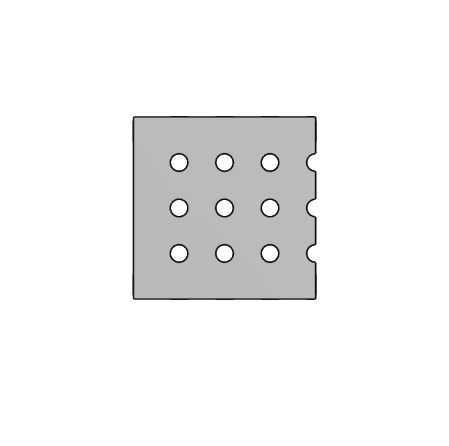
You can download the DXF files for the Coral Hood pieces for a 1:1 scale pattern or CNC routing here:

* [Coral Hood Part 1 (Sides)](https://revrobotics.com/content/docs/2025-StarterBot-CoralHood_1.dxf)
* [Coral Hood Part 2 (Top and Bottom)](https://revrobotics.com/content/docs/2025-StarterBot-CoralHood_2.dxf)
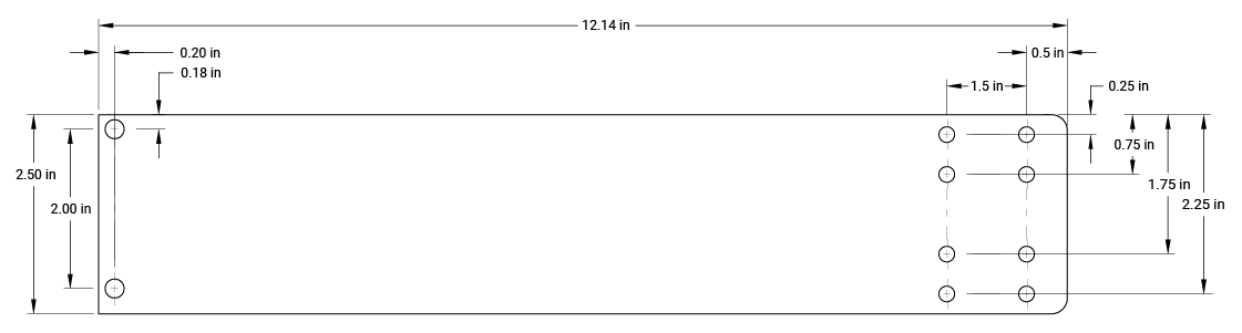
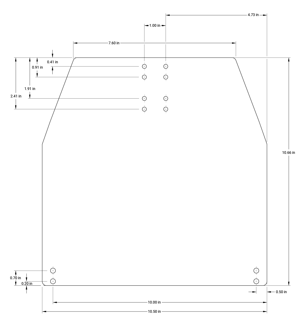
  {% endhint %}

Part 1 (Sides)

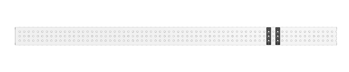
<figure><img src="/files/V7sGEihQh4UqYn7p1PaK" alt=""><figcaption><p>Part 1 (Sides)</p></figcaption></figure>

Part 2 (Top and Bottom)

<figure><img src="/files/FQzxRjaZfEUFixLyXMag" alt=""><figcaption><p>Part 2 (Top and Bottom)</p></figcaption></figure>

## Algae Intake

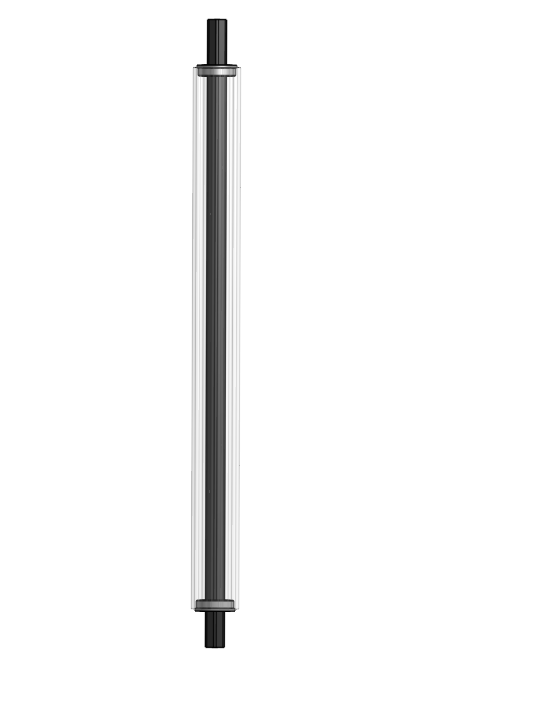
<table data-header-hidden><thead><tr><th></th><th></th><th data-hidden></th></tr></thead><tbody><tr><td><p></p><ol><li>Get:</li></ol><ul><li>2 - MAXTube Internal Support 2x1</li><li>1 - MAXTube 2x1 with MAX Pattern - cut to 9in</li></ul><p>Insert two MAXTube Internal Supports into each end of the MAXTube pieces. Take care to ensure they do not fall out before securing them in the next step.</p></td><td><img src="/files/tLsF8EbSBWXpHUAw5llP" alt="" data-size="original"></td><td></td></tr><tr><td><ol start="2"><li>Get:</li></ol><ul><li>1 - MAXPlanetary System 45:1 with 2.5in tapped output shaft</li><li>1 - 1/2in Rounded Hex Bearing </li><li>2 - #10-32 Button Head Screws x 1.5in</li></ul><p>Attach the MAXPlanetary System as shown. Insert a 1/2 bearing on the opposite side of the MAXPlanetary System to support  the output shaft.</p></td><td><img src="/files/VFabYALEtD4dNZQyXxmA" alt="" data-size="original"></td><td></td></tr><tr><td><ol start="3"><li>Get:</li></ol><ul><li>1 - 20DP Gear - 1/2in Hex - 20T</li><li>1 - 1/2in Hex Shaft Spacer - 1/4in</li><li>1 - 1/2in Hex Shaft Spacer - 1/8in</li><li>2 - 1/2in Hex Shaft Spacer - 1/16in</li><li>1 - #10-32 Shaft End Screw</li></ul><p>Slide onto the output shaft, in this order, a 1/16in spacer, a 20T gear, a 1/4in spacer, a 1/8in spacer, a 1/16in spacer, and a shaft end screw. </p></td><td><img src="/files/qUjo7g8p4oNnC9KD7uWn" alt="" data-size="original"></td><td></td></tr><tr><td><ol start="4"><li>Get:</li></ol><ul><li>1 - 1/2in Rounded Hex Shaft - 2.5in tapped</li><li>2 - 1/2in Rounded Hex Bearing </li><li>1 - #10-32 Shaft End Screw</li><li>1 - 1/2in Hex Shaft Spacer - 1/16in</li></ul><p>Insert two 1/2in bearings into the MAXTube as shown. Slide a 1/6in spacer onto left side as shown and secure with a shaft end screw.</p></td><td><img src="/files/jgf1osUj2HSlgCyTGX95" alt="" data-size="original"></td><td></td></tr><tr><td><ol start="5"><li>Get:</li></ol><ul><li>1 - MAXSpline Shaft cut to 1.125in</li><li>1 - MAXSpline Shaft Endcap - 1/2in Hex</li><li>1 - Bushing - Plastic - 13.75mm ID - 1in OD</li></ul><p>Slide onto the hex shaft as shown in this order, a MAXSpline Shaft Endcap, a 1.125 cut section MAXSpline Shaft, and a 1in plastic bushing. </p></td><td><img src="/files/WeE9TbcDxCawgfQNB76F" alt=""><br><img src="/files/GRl3ptQeNbGjnhJnDp2h" alt=""></td><td></td></tr><tr><td><ol start="6"><li>Get:</li></ol><ul><li>1 - 20DP Gear - MAXSpline - 60T</li><li>1 - MAXSpline Spacer - 1/4in</li><li>1 - MAXSpline Spacer - 1/16in</li></ul><p>Slide onto the output shaft, in this order, a 60T gear, a 1/4in spacer, a 1/16in spacer.</p></td><td><img src="/files/jsfOBIlrsyPlb9AzvWad" alt="" data-size="original"></td><td></td></tr><tr><td><ol start="7"><li>Get:</li></ol><ul><li>1 - MAXSpline Pillow Block</li><li>1 - MAXHub - Structural</li><li>1 - #10-32 Shaft End Screw</li></ul><p>Slide onto the output shaft a MAXSpline pillow block and then insert a MAXHub into the pillow block. Secure the shaft with a shaft end screw.</p></td><td><img src="/files/xgvVJk0g20FFK2XezOLv" alt="" data-size="original"></td><td></td></tr><tr><td><ol start="8"><li>Get:</li></ol><ul><li>1 - MAXTube 2x1 with MAX Pattern - cut to 9in</li><li>1 - 1/2in Round Hex Shaft - 2in Tapped</li><li>1 - 1/2in Hex Shaft Spacer - 1/4in</li><li>1 - 1/2in Hex Shaft Spacer - 1/8in</li><li>1 - Bushing - Plastic - 13.75mm ID - 1in OD</li></ul><p>Insert two plastic bushings into each side of the MAXTube. Slide a 2in hex shaft through the bushings then slide a 1/4in spacer onto the left side as shown and a 1/8in spacer and shaft end screw on the right.</p></td><td><img src="/files/fkAQ9zr1oQ4q3DcV3gWk" alt="" data-size="original"></td><td></td></tr><tr><td><ol start="9"><li>Get:</li></ol><ul><li>1 - MAXSpline Pillow Block</li><li>1 - MAXHub - Structural</li><li>1 - MAXHub - 1/2in Hex - Aluminum</li><li>1 - #10-32 Button Head Screws x 3/4in</li><li>#10-32 Low Profile Nylon Lock Nut</li></ul><p>Insert a structural and a 1/2in hex MAXHub into a MAXSpline Pillow Block and secure with a 3/4in screw and lock nut as shown.  </p></td><td><img src="/files/yLVPfViLlVBqm7UAT4sE" alt="" data-size="original"><br><img src="/files/rFb6sNrYcmmBruflVyUv" alt=""></td><td></td></tr><tr><td><ol start="10"><li>Get:</li></ol><ul><li>1 - #10-32 Shaft End Screw</li></ul><p>Slide the pillow block onto the 1/2in hex shaft and secure it with a shaft end screw. </p></td><td><img src="/files/6kYQuyxkEMLBdAnlre0x" alt="" data-size="original"></td><td></td></tr><tr><td><ol start="11"><li>Get:</li></ol><ul><li>1 - MAXSpline cut to 17-3/4in</li></ul><p>Slide the two MAXTube sections onto a 17-3/4in cut MAXSpline shaft.  Leave 1-1/2in on the left side as shown and 2-1/8in on the right side as shown. <br><br>Note: Significant force may be needed</p></td><td><img src="/files/Q8EVvaiKabXP3YjhHVIU" alt="" data-size="original"></td><td></td></tr><tr><td><ol start="12"><li>Get:</li></ol><ul><li>1 - MAXTube cut to 15in</li><li>2 - MAXSpline Shaft Collar</li></ul><p>Slide the MAXTube section onto the shaft from the previous step. Secure the MAXTube with shaft collars as shown. </p></td><td><img src="/files/aGLRCO64gedjBQ86yBVy" alt="" data-size="original"></td><td></td></tr><tr><td><ol start="13"><li>Get:</li></ol><ul><li>2 - MAXHubs - 1/2in Hex - Plastic</li><li>1 - #10-32 Button Head Screws x 3/4in</li></ul><p>Slide the MAXHubs into the MAXTube as shown. Secure the MAXHubs with a screw.</p></td><td><img src="/files/zJHHozu1W3CAFnZ8mxyb" alt="" data-size="original"></td><td></td></tr><tr><td><ol start="14"><li>Get:</li></ol><ul><li>1 - MAXSpline cut to 14-3/4in</li><li>1 - 1/2in Rounded Hex Shaft cut to 16-3/4in</li><li>2 - 1/2in Rounded Hex Bearing - Flanged - 1in OD</li></ul><p>Slide the section MAXSpline shaft onto the hex shaft, then slide the two bearings onto hex shaft and into the MAXSpline as shown.</p></td><td><img src="/files/vjyJ4uwPm5NQJR2DOq1U" alt="" data-size="original"></td><td></td></tr><tr><td><ol start="15"><li>Get:</li></ol><ul><li>4 - Grip Wheel - 4in - MAXSpline - Hard</li><li>1 - RT25 Plastic Pulley - MAXSpline - 24T</li></ul><p>Slide onto the MAXSpline the Grip Wheels and pulley as shown.</p></td><td><img src="/files/RAPATLYXXQrZCbKCcyVg" alt="" data-size="original"></td><td></td></tr><tr><td><ol start="16"><li>Get:</li></ol><ul><li>1 - MAXTube with MAX Pattern - 15in</li><li>1 - MAXTube Internal Spacer</li><li>1 - MAXHub - Structural</li><li>1 - MAXHub - 1/2in Hex - Aluminum</li><li>1 - #10-32 Button Head Screws x 3/4in</li></ul><p>Slide into the MAXTube the internal spacer. Insert the MAXHubs and secure them with a screw as shown.</p></td><td><img src="/files/HeEJ2ReayjbQJrlW0glI" alt="" data-size="original"></td><td></td></tr><tr><td><ol start="17"><li>Get:</li></ol><ul><li>1 - MAXTube from the previous step</li><li>1 - RT25 Belt - 1/2in Width - 88T</li><li>1 - MAXSpline Spacer - 1/2in</li><li>1 - MAXSpline Spacer - 1/8in</li><li>1 - MAXSpline Shaft Collar</li><li>1 - Shaft End Screw</li></ul><p>Wrap a 88 tooth belt around the pulley on the MAXSpline. Slide onto the right MAXSpline the 1/8in and 1/2in spacer as shown. Slide the MAXTube from the previous step onto the MAXSpline and 1/2in hex as shown then secure the 1/2in hex shaft with a shaft end screw and the MAXSpline with a MAXSpline Shaft Collar. </p></td><td><img src="/files/PHqrZGmZO9IVloCK2z3a" alt="" data-size="original"></td><td></td></tr><tr><td><ol start="18"><li>Get:</li></ol><ul><li>1 - 3:1 MAXPlanetary System with a NEO Vortex and a 1-3/4in output</li></ul><p>Assemble a 3:1 MAXPlanetary System with a NEO Vortex and a 1-3/4in output.</p></td><td><img src="/files/UrWQKriAhZSRyfvsGUoH" alt="" data-size="original"></td><td></td></tr><tr><td><ol start="19"><li>Get:</li></ol><ul><li>1 - MAXSpline Bearing Block</li><li>1 - 1/2in Hex Spacer - 1/8in</li><li>1 - 1/2in Hex Spacer - 1/2in</li><li>2 -  #10-32 Button Head Screws x 5/8in</li><li>1 - RT25 Pulley - 1/2in Hex - 16T</li></ul><p>Slide the 1/8in and 1/2in spacers onto the output shaft. Install the bearing block onto the MAXPlanetary Output with two screws. Slide the 16T pulley onto the output shaft. </p></td><td><img src="/files/dvrCW3mPiqAYjRkTelGx" alt="" data-size="original"></td><td></td></tr><tr><td><ol start="20"><li>Get:</li></ol><ul><li>2 - MAXSpline Bearing Blocks</li><li>1 - 1/2in Rounded Hex Bearing</li><li>4 - #10-32 Button Head Screws x 2-1/2in</li><li>4 - #10 Spacers - 3/4in</li></ul><p>Wrap the 88 tooth belt around the 16T pulley. Insert a 1/2in bearing into a bearing block then use the two bearing blocks and the MAXPlanetary system from the last step to to mount the MAXPlanetary System and create tension on the belt. </p></td><td><img src="/files/ZgRxFujEg5r6Xb8DG6ty" alt=""><br><br><img src="/files/oVdGYmoIJzXJrRZOeBHw" alt=""><br><br><img src="/files/0nJEeAEbz3u5gXe9S1Ud" alt=""></td><td></td></tr><tr><td><ol start="21"><li>Get:</li></ol><ul><li>1 - 1/2in x 1/2in MAXTube cut to 4in</li><li>1 - #10 Spacer - 1/4in</li><li>1 - #10 Socket Head Screw x 2-1/2in</li><li>1 - #10-32 Low Profile Nylon Lock Nut</li></ul><p>Secure the 1/2in MAXTube through the MAXSpline Spacer and MAXTube as shown.</p></td><td><img src="/files/SRmygrSzcz5icMLwwE6e" alt="" data-size="original"></td><td></td></tr><tr><td><p></p><ol start="22"><li>Get:</li></ol><ul><li>1 - 1/2in x 1/2in MAXTube cut to 9-1/2in</li><li>1 - #10 Socket Head Screw x 1-1/2in</li><li>2 - #10-32 Low Profile Nylon Lock Nut</li></ul><p>Secure the 1/2in MAXTube with two nuts as shown, leave this loose enough for the MAXTube to roate around the screw.</p></td><td><img src="/files/hkszkKLRboKWpdqxdYIN" alt="" data-size="original"></td><td></td></tr><tr><td><p></p><ol start="23"><li>Get:</li></ol><ul><li>1 - 3/8in Nut Strip - 5 Pos</li><li>3 - #10-32 Button Head Screws x 1/2in</li><li>1 - #10-32 Ball Joint Rod End - Left-hand Threaded</li></ul><p>Secure the nut strip in MAXTube with three screws as shown. Screw the tie rod end in as shown.</p></td><td><img src="/files/mK2hJ9GMPNvLhn3ZKQUU" alt="" data-size="original"></td><td></td></tr></tbody></table>

## Final Assembly

<table data-header-hidden><thead><tr><th></th><th></th><th data-hidden></th></tr></thead><tbody><tr><td><ol><li>Get:</li></ol><ul><li>Single Stage Elevator Assembly</li><li>Drivetrain Assembly</li><li>4 - #10-32 Button Head Hex Drive Screw x 2-1/2in</li><li>4 - #10-32 Button Head Hex Drive Screw x 3/4in</li><li>4 - #10 Spacers - 1/8in</li></ul><p>Secure the Elevator to the Drivetrain with four 2-1/2in screws from the underside of the drivetrain as shown. <br><br>Secure the bracing to the endcaps on the drivetrain. You should need to adjust the tie rod ends until the bracing is rigid, this may take two people to "pull" on the bracing to provide tension. The Elevator should be completely rigid with no movement independent from the drivetrain. <br><br>Note: The bracing on the backside of the Starterbot do cross and attach to opposite sides on the endcaps, see the second image. </p></td><td><img src="/files/sYrtE6fPPdkMf1bAQmC3" alt="" data-size="original"><br><img src="/files/LBk26KpcR6bz2uaHr9cF" alt=""></td><td></td></tr><tr><td><ol start="2"><li></li></ol><p>Lift the single stage till you have at least ten inches showing, insert a bolt or metal screwdriver that is at least 2-1/2in in length through the static stage and through the single stage to keep the Elevator lifted.<br><br>Note: DO NOT use Zip Ties to hold up the elevator.</p></td><td><img src="/files/4yJX95CG5wiaTnL6wo28" alt="" data-size="original"><br></td><td></td></tr><tr><td><p></p><ol start="3"><li>Get:</li></ol><ul><li>Intake Assembly</li><li>2 - #10-32 Button Head Hex Drive Screw x 1-1/2in</li><li>2 - 1/2in Hex Shaft Spacer - 1/16in</li></ul><p>Slide a 1/16in spacer onto the 1/2in hex shaft of the intake then mount the intake to the elevator through the holes with the internal support as shown. </p></td><td><img src="/files/TXl80srxBD2MIRCpa7sn" alt="" data-size="original"></td><td></td></tr><tr><td><ol start="4"><li>Get:</li></ol><ul><li>1 - #25 Chain that is 163links with a turnbuckle</li></ul><p>Wrap the chain around the sprocket on the Intake and the MAXPlanetary system on the Elevator. The turnbuckle should be near the sprocket with the Intake down. Adjust the location of the turnbuckle if it makes contact with the sprocket on the intake or MAXPlanetary. </p></td><td><img src="/files/MCaMAkUhTXtbadQVhMsE" alt="" data-size="original"></td><td></td></tr><tr><td><ol start="5"><li>Get:</li></ol><ul><li>2 - #25 Chain that is 287 links with a turnbuckle</li></ul><p>Wrap the chain around the 16T sprockets on the Elevator and the 16T sprockets on the Drivetrain. The turnbuckle should be near the sprockets on the Elevator with the Elevator down. Adjust the location of the turnbuckle if it makes contact with the sprockets on the Elevator or Drivetrain shaft.</p></td><td><img src="/files/2dSFzt04gwYhOode19LH" alt="" data-size="original"></td><td></td></tr><tr><td><ol start="6"><li>Get:</li></ol><ul><li>10 - M3 Hex Cap Screws x 20mm</li><li>10 - M3 Nyloc Nuts</li><li>2 - Chain Adapter Blocks</li><li>6 - #10-32 Button Head Hex Drive Screw x 1/2in</li></ul><p>Attach a Chain Adapter Block to both Elevator chains with the M3 screws and nuts and then attach the adapters to the nut strips on the elevator with the #10-32 screws as shown.</p></td><td><img src="/files/5RJHGKVuNOvYX9DNqKjj" alt="" data-size="original"><br><img src="/files/zKGHAzsTNXS9jLrNkbKU" alt=""></td><td></td></tr><tr><td><ol start="7"><li>Get:</li></ol><ul><li>4 - #10-32 Button Head Hex Drive Screw x 2-1/2in</li><li>4 - #10-32 Low Profile Nylon Lock Nut</li></ul><p>Attach the Ball Intake to the Drivetrain using the screws and nuts as shown.</p></td><td><img src="/files/XSrmtBqqOpeO6T13nord" alt="" data-size="original"><br><img src="/files/bJk9Bc3LsT5bXkpD1c8H" alt=""></td><td></td></tr><tr><td><ol start="8"><li>Get:</li></ol><ul><li>1 - #10-32 Button Head Hex Drive Screw x 1-3/4in</li><li>1 -  #10-32 Low Profile Nylon Lock Nut</li><li>1 - #10 Spacers - 1/4in</li></ul><p>Lift the Elevator, then attach the Ball Intake brace to the Elevator with the nut and spacer on the outside of the elevator. </p></td><td><img src="/files/BIs85s4LyLv9eTxgNKtL" alt="" data-size="original"></td><td></td></tr><tr><td><ol start="9"><li>Get:</li></ol><ul><li>1 - Zip Tie</li><li>1 - Surgical Tubing</li></ul><p>Make a loop with a Zip Tie at the corner of the bracing on the Ball Intake, then make a loop of surgical tubing through the Zip Tie loop and the nut strip on the ELevator bracing as shown. This should be tight enough to pull the Ball Intake but not snap when the intake is deployed. </p></td><td><img src="/files/iMMqJHnJ3PMF7kODxv3S" alt="" data-size="original"></td><td></td></tr><tr><td><ol start="10"><li>Get:</li></ol><ul><li>All Necessary Electronics</li></ul><p>Install your electronics in your preferred locations, we have suggested </p></td><td><img src="/files/bKlK3TWTAEJkWqu6zAxh" alt="" data-size="original"></td><td></td></tr><tr><td>You are done! </td><td><img src="/files/4hpzuEx39eeVJTHjMyT7" alt="" data-size="original"></td><td></td></tr></tbody></table>


---

# Agent Instructions: Querying This Documentation

If you need additional information that is not directly available in this page, you can query the documentation dynamically by asking a question.

Perform an HTTP GET request on the current page URL with the `ask` query parameter:

```
GET https://docs.revrobotics.com/frc-kickoff-concepts/2025/build-guide.md?ask=<question>
```

The question should be specific, self-contained, and written in natural language.
The response will contain a direct answer to the question and relevant excerpts and sources from the documentation.

Use this mechanism when the answer is not explicitly present in the current page, you need clarification or additional context, or you want to retrieve related documentation sections.