Loading...
Loading...
Loading...
Loading...
Loading...
Loading...
Loading...
Loading...
Loading...
Loading...
MAXMotion Position Control is a second-degree closed loop controller, allowing for smooth and consistent motions from one position to another by limiting both the velocity and acceleration of the motor. These can be configured via the MAXMotion Parameters, setting a target acceleration and a "cruise" velocity. The motor will spin up, honoring the acceleration target, hold speed at the cruise velocity, and then slow down honoring the acceleration target to arrive at the setpoint. MAXMotion updates its motion profile every 10ms and the underlying PID controller every 1ms, which makes it extremely fast and responsive.
MAXMotion generates a profile containing all the key transition points between the current position and the setpoint and uses that to calculate intermediate positions for the PID controller to follow.
Each point along the profile is a target for the PID controller at the point in time it corresponds to. If, at some point in time, the actual measured position is more than the configured Allowed Profile Error away from the profile, the profile will be regenerated from the current position and velocity. While the mechanism is within that margin, it will continue to track the same profile. This makes tuning easy and makes motions consistent and accurate.
The SPARK Feedforward system was designed with MAXMotion in mind, and MAXMotion can take advantage of all of its features.
The first step of setting up MAXMotion is to configure the PID feedforwards, as explained on the feedforward page. The kV and kA values from a calculator, converted to appropriate units, or from a tool like SysID are perfect starting points for tuning.
There are 3 primary constants to configure for MAXMotion:
Cruise Velocity: this is the speed you want the motion to hold through the middle of its path
Maximum Acceleration: this is the acceleration you want to use to speed up and slow down the motion
Allowed Profile Error: this is the amount of position deviation from the profile that is allowed before the profile is regenerated
Ensure the mechanism is free to move and note any mechanical limits
Set up the for the mechanism. Note that these may not provide expected results until other values are setup
Set P to a very small number, relative to your position units. For the default units, kP = 0.01 is a good starting point. Keep in mind that kP will be multiplied by your position error and then become duty cycle percent output, so pick a "small" value relative to what your position error is expected to be
A well-tuned MAXMotion controller will:
Track position, velocity, and acceleration closely and accurately
Respond quickly to a change in setpoint
Not stutter or reset
Move smoothly and in a controllable way
After tuning your constants, calling MAXMotion is as simple as passing in the setpoint to the controller.
API Docs:
API Reference:
Smart Motion used a different method for smooth second-degree motion control, but MAXMotion can be applied anywhere Smart Motion was previously. Maximum velocity and acceleration constants may be transferable, but should be tested with caution. All other constants will need re-tuned from scratch, including all PIDs.
MAXMotion has several improvements over Smart Motion, and should offer better consistency, a better tuning experience, better position retention, and an all-around better user experience. It is highly recommended to migrate all systems using Smart Motion to MAXMotion.
kP
This is the position-tracking gain. This represents how much voltage is applied proportionally to the position error. Increasing it will make the mechanism move toward the position target more quickly, but increasing it too much will cause overshooting and stuttering.
kI
This is the integral gain, which is not often recommended for FRC use.
kD
This is the derivative gain, which helps track velocity within the position controller. For better velocity tracking, kV is a better choice.
kS
This is the static gain, which helps overcome a constant resistance like friction in a gearbox. It should be set to the maximum voltage in either direction that doesn't make the mechanism move at all, where any more causes motion. Increasing it will improve precision and make motions in different directions more consistent, but increasing it too much will cause jitter.
kV
This is the velocity-tracking gain. Increasing it will increase the voltage output proportionally to the velocity target, and will help track velocity more closely. Increasing it too much will cause overshooting on velocity or general instability.
kA
This is the acceleration-tracking gain. Increasing it will help track acceleration more closely, but increasing it too much will cause instability. It will make a noticeable difference in velocity tracking during acceleration and deceleration.
kG and kCos
These are gravity feedforwards, that help hold position against gravity and remove the gravity factor from the position and velocity tracking of the other constants. For more information on these gains, see
Set the Allowed Profile Error to a high number relative to your units and the distance to your setpoint. For most motions at the default units, an Allowed Profile Error of 1 Rotation is enough to get started. If the results are confusing, especially if the acceleration targets appear to be too low, increase this. Increasing this value will let the motion continue for a longer period before regenerating the profile, which may uncover the root of a tuning issue
Set up a method to retrieve relevant info
If running a robot program, use NetworkTables to post this information
Several of these values can be fetched from the SparkClosedLoopController object
A dashboard like Glass or AdvantageScope can help graph and record these values
In the REV Hardware Client, use the Telemetry tab to enable this information
Good information to watch while tuning:
Position
Velocity
Applied Output
Note that fetching all these values may require modifying the Status Frame Periods for certain parameters as the CAN bus or the SPARK device reaches its limit. If the device stops responding and many Status Frames are timing out, power cycle all devices on the bus to clear the errors and try reducing traffic by increasing status frame periods
Graphing all the positions and all the velocities on 2 graphs will help this process
Tuning for your mechanism using Simulation is a safe, good way to start, but will probably still need further tweaking to make the actual mechanism's motion perfect
Be very careful, as this tuning process could cause your mechanism to move in unpredictable or unexpected ways if the constants are off, particularly if your units don't match up
Repeat the following process until the results are satisfactory
Run and record a motion to a known setpoint
If the motion is jittery or shaky, reduce kP. If your Allowed Profile Error is small, increase it to a large number while diagnosing issues
If the motion shoots to a high, uncontrollable velocity immediately, increase P to a larger number. With too small of a P value, the feedforwards are sensitive to tiny inaccuracies, but by increasing P it will increase this tolerance. If this persists, reduce your feedforward values, specifically kV
If the MAXMotion Position Setpoint jumps or spikes and resets more than a few times, increase the Allowed Profile Error. This won't contribute to fixing the issue, but will let you better observe the behavior and identify other factors.
If the motion is asymmetrical up vs down, recalculate kG and kS or try determining them experimentally
If the velocity lags behind the target velocity, increase kV
If the velocity overshoots the target velocity, decrease kV
If the position lags behind the target, increase kP slightly
If the mechanism overshoots the setpoint, reduce kV (or, if that doesn't fix it, kS)
If the motion is stable, smooth, and consistent, the the position and velocity targets are reached consistently, the mechanism doesn't overshoot the setpoint, and the MAXMotion Position Setpoint doesn't seem to "jump", reduce the Allowed Profile Error, increase the Cruise Velocity, or increase the Max Acceleration slightly
Repeat this process until you have the speed, smoothness, and accuracy that you want
Move quickly
Not overshoot the setpoint
The acceleration will be set as high as is smooth without hitting the current limit
The velocity will be set as high as is achievable and smooth
The allowed profile error will be as small as possible
Cruise Velocity
This is the top of the trapezoid, the velocity that is sustained through the center stage of the motion. Increasing it beyond what is achievable will result in a triangular "trapezoid" on you Velocity graph.
Maximum Acceleration
This is how quickly the mechanism accelerates. Increasing it too much will draw a lot of current, and may hit the current limits or stall the motors.
Allowed Profile Error
m_controller.setSetpoint(setPoint, SparkBase.ControlType.kMAXMotionPositionControl);using namespace rev::spark;
m_controller.SetSetpoint(setPoint, SparkBase::ControlType::kMAXMotionPositionControl);This is how "loose" the profile is, and how far your mechanism can get from the profile before the profile is regenerated. For tuning, it's helpful to set this to a large value so you can see the behavior without the profile resetting, but the end goal for your motion should be to minimize this margin.
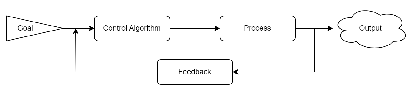
A Closed-Loop Control System in its most basic form is a process that uses feedback to improve the accuracy of its outputs. Closed-Loop Control Systems, sometimes referred to as Feedback Controllers, are frequently used when maintaining or reaching a steady output is important or if the system may have outside influences that could affect the system's output.
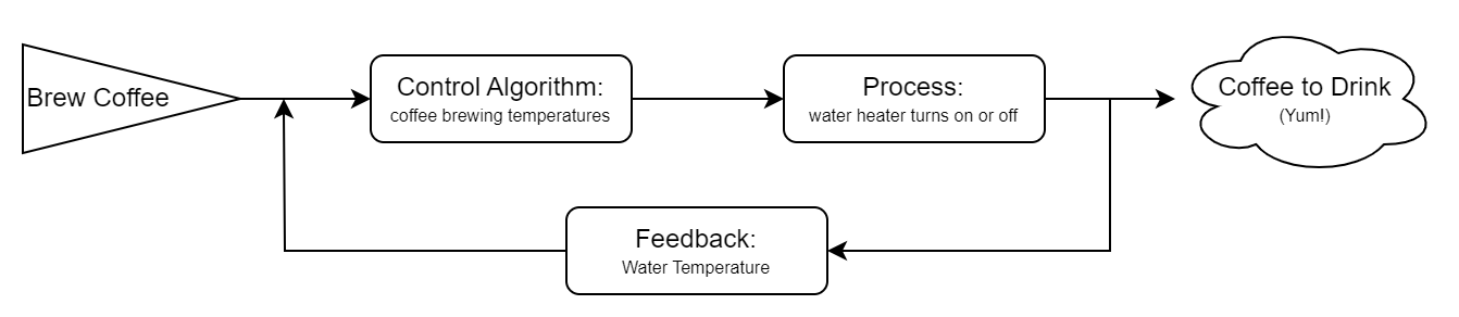
A simple example using this type of Control is an automatic coffee maker. In its Closed-Loop Control System, the output is hot coffee and the process we are getting feedback on is the heating of the water. If the coffee maker receives feedback that the water is cold, it will start to heat the pot. When the water is almost hot enough to brew the coffee, the control algorithm will continue to heat the water until the correct goal temperature has been reached. Once the water reaches it's goal temperature, or if it gets too hot, the system will stop heating the water and wait until it receives feedback that the heater needs to begin again.
Closed-Loop Control is a staple of complex FRC mechanism programming. WPILib offers to allow teams to run PID loops on the roboRIO, but they require manual setup in your team's code, need additional configuration to run at high frequencies, and may require specifically-configured feedback devices for fast responses.
With a PID loop onboard a SPARK Motor Controller, the setup is simple, doesn't clutter your code, and the loop is updated every 1ms, increasing the responsiveness and precision of the controller. Even when using a more complex control algorithm on the roboRIO, it's still recommended to put as much processing on the motor controller as possible. The PID controller onboard the SPARK can also be configured and tuned with the REV Hardware Client, allowing for a much faster tuning process that doesn't rely on your other subsystems.
MAXMotion Velocity Setpoint
Setpoint
Current Draw
Configuring SPARK PID with REVLib can be done in a couple of lines and fits right into the configuration of the motor controller.
Setting a setpoint for the PID is just as easy, whether you want to set a position or velocity or even use a motion profile.
Both the SPARK MAX and SPARK Flex can operate in several closed-loop control modes, using sensor input to tightly control the motor velocity, position, or current. The internal control loop follows a standard PID algorithm and incorporates several feedforward terms to account for known system dynamics. This allows the motor to follow precise and repeatable motions, useful for complex mechanisms.
Additionally, an arbitrary feedforward signal is added to the output of the control loop after all calculations are done. The units for this signal can be selected as either voltage or duty cycle. This feature allows more advanced feedforward calculations to be performed by the controller. This can be useful for systems with more complex dynamics than can be represented by the SPARK feedforward.
SparkFlexConfig config = new SparkFlexConfig()
    .closedLoop.pid(0.01, 0, 0.001);
spark.configure(config, ResetMode.kNoResetSafeParameters, PersistMode.kNoPersistParameters);SparkClosedLoopController closedLoopController = spark.getClosedLoopController();
closedLoopController.setSetpoint(10, ControlType.kVelocity); // 10 RPMFor a detailed technical and mathematical description of each term and its effect, the WPILib docs page on PID is a good resource.
In FRC, PID loops are used in many types of mechanisms, from flywheel shooters to vertical arms. These need to be tuned to different constants, depending on the units they use and the physical design of the mechanism, however the process to find these constants is roughly the same.
Most teams find success using controllers tuned primarily with P and D, using a Feedforward to account for steady-state error.
P, the proportional gain, is the primary factor of the control loop. This is multiplied by the error and that gain is added to the output. This does the heavy lifting of the motion, pushing the motor in the direction it needs to go.
I, the integral gain, is not often recommended in FRC. It is useful for eliminating steady-state error, or error that the other gains leave behind and cannot address. It accumulates the error over time and multiplies it by the I gain, gradually increasing the power it supplies until that has evened out. If it is needed, it's recommended to use a limited to prevent I windup. For FRC purposes, Feedforward gains are recommended to eliminate steady-state error instead.
The derivative gain, D, is used to tune out oscillation and dampen the motion. It resists motion, decreasing power when the mechanism is moving. A good balance of P and D is needed to make a smooth motion with no oscillation.
Several guides for PID tuning are available, such as . It may be useful to consult multiple, especially those available that reference your specific mechanism.
Any method for PID tuning will start with the same concept, however, regardless of mechanism. Before you can tune your mechanism, you should setup a graph of the setpoint and that measured value, either through the or a similar utility. This will allow you to analyze each test and properly evaluate the changes to make.
To then tune a basic PID loop, follow the steps below:
Set all constants (P, I, D, etc) to 0
Ensure the mechanism is safe to actuate. This process will spin the motor, potentially at unexpected speeds and in unexpected directions
Check the direction of the motor, and invert it if needed so that positive output is in the desired direction
MAXMotion Velocity Control utilizes the to improve upon velocity control. Honoring the maximum acceleration, MAXMotion Velocity Control will speed up your flywheel or rotary mechanism in a controlled way, reducing power draw and increasing consistency.
MAXMotion Velocity Control utilizes an internal velocity closed-loop controller, so transitioning from Velocity Control mode to MAXMotion Velocity Control is as simple as setting a maximum acceleration and changing the setSetpoint call.
It is called as seen below:
API Docs:
API Reference:
Current Control uses a PID controller to run the motor at a consistent current, providing a consistent torque. The PID controller is run using the setpoint, in Amps, and the internally measured current draw.
It is called as shown below:
API Docs:
API Reference:
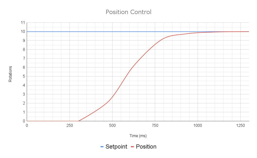
Position Control is used to point the motor in a specific direction. It takes a setpoint in rotations (or whatever unit your selected encoder's position conversion factor is in) and uses the PID loop to move to that position. The Position control mode pipes directly into a PID controller with the configured encoder.
A properly tuned Position control loop should respond quickly and accurately to a setpoint change and should not oscillate around the target.
To run the motor in Position control mode, set the PID Controller setpoint as shown below.
API Docs:
API Reference:
Set P to a very small number, relative to the units you are working in
Set a target for the motor to move to. Ensure this is within the range of your mechanism.
Gradually increase P until you see movement, by small increments
Once you see motion, increase P by small increments until it reaches the target at the desired speed
If you see oscillation, decrease P or begin to increment D by a small amount. A precisely tuned P gain is better than a D gain, but a D gain may be needed to counteract the dynamics of the system
Continue to adjust these parameters until the motion is quick, precise, and repeatable
If your motion seems jittery, try reducing your PID constants, especially P. If the underlying velocity PID outruns the acceleration target, the motion may seem jittery and the velocity will not increase smoothly.
Make sure your units are correct: maximum velocity is set in RPM by default and maximum acceleration is set in RPM per second by default.
At low speeds, the acceleration may seem wobbly or inconsistent if the loop has been tuned for higher speeds or vice versa. If both are needed, try tuning separate PIDs and switching between slots when needed. This may be easier than finding those perfect constants that work beautifully across the board.
using namespace rev::spark;

m_controller.SetSetpoint(setPoint, SparkBase::ControlType::kMAXMotionVelocityControl);m_controller.setSetpoint(setPoint, ControlType.kMAXMotionVelocityControl);using namespace rev::spark;
m_controller.SetSetpoint(setPoint, SparkBase::ControlType::kCurrent);m_controller.setSetpoint(setPoint, ControlType.kCurrent);using namespace rev::spark;
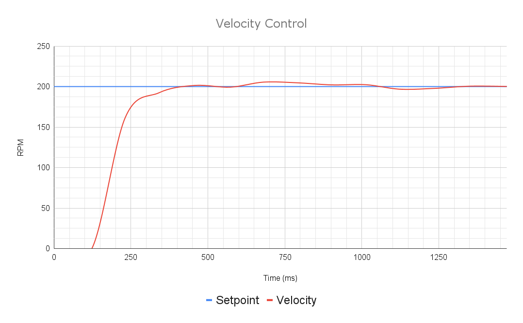
m_controller.SetSetpoint(setPoint, SparkBase::ControlType::kPosition);m_controller.setSetpoint(setPoint, ControlType.kPosition);Velocity Control uses the PID controller to run the motor at a set speed in RPM (or configured conversion factor units).
It is called in the same way as Position Control:
API Docs:
API Reference:
m_controller.setSetpoint(setPoint, ControlType.kVelocity);using namespace rev::spark;
m_controller.SetSetpoint(setPoint, SparkBase::ControlType::kVelocity);Setpoint
Rotations
Position Conversion Factor
There are two configurable Conversion Factors on each Encoder type that can be used to account for gear ratios and unit conversions in the motor control logic. These are applied independently and the velocity factor does not rely on the position factor, so different units can be used for each.
Positions read from the feedback encoder are multiplied by the Position Conversion Factor before being processed by the closed-loop controller.
Velocities read from the feedback encoder are multiplied by the Velocity Conversion Factor before being processed by the closed-loop controller.
The velocity conversion factor is completely independent of the position conversion factor, so both need to be set to change both units.
All accelerations on the SPARK controllers are in terms of velocity per second, where the velocity is in units specified by the Velocity Conversion Factor.
Closed loop PID control and MAXMotion motion profiled control are excellent tools for precisely and reactively controlling mechanisms on your robot, but the effectiveness of these tools can be increased further with the introduction of Feed Forward terms. A feed forward (or feedforward) controller is an additional calculation that helps factor system dynamics like gravity and resistance into your closed loop movements, which can be especially helpful on heavy systems.
that behave similarly to the SPARK motor controllers internal calculations and also have an The SPARK feed forward system is designed to drop-in to many of the use cases of these utilities, so much of the information on them is transferable, though you may need to watch your units.
The SPARK feed forward system has the added benefits of directly integrating with MAXMotion, being able to use high feedback frequencies without increased CAN bus traffic or additional configuration, being easy to setup and use, and conserving processing resources on your robot controller.
For more information on these terms, see their descriptions below
10:1 Gearbox, Rotations at output
1/10 (0.1)
Distance in inches traveled with a 6in diameter wheel
6π (18.8495559215)
Degrees per Second
360/60 (6)
Radians per Minute
2π (6.28318530718)
Radians per Second
2π/60 (0.10471975512)
Encoder Position
Rotations
Position Conversion Factor
Encoder Velocity
RPM
Velocity Conversion Factor
Applied Output
Duty Cycle
kP
Duty cycle per rotation
Position Conversion Factor
kI
Duty cycle per (rotation*ms)
Position Conversion Factor
kD
(Duty cycle*ms) per rotation
Position Conversion Factor
kS
Volts
kV
Volts per RPM
Velocity Conversion Factor
kA
Volts per RPM/s
Velocity Conversion Factor
kG
Volts
kCos
Volts per Rotation
MAXMotion Cruise Velocity
RPM
Velocity Conversion Factor
MAXMotion Maximum Acceleration
RPM/s
Velocity Conversion Factor
MAXMotion Allowed Profile Error
Rotations
Position Conversion Factor
Default (Revolutions)
1
Degrees
360
Radians
Default (RPM)
1
Revolutions per Second
1/60 (0.01666666666)
Degrees per Minute
2π (6.28318530718)
360
kS
Volts
kV
Volts per velocity
Volts per motor RPM by default
kA
Volts per velocity/s
Volts per motor RPM/s by default
The SPARK Feed Forward system includes 5 terms and one additional constant, each of which apply to some control modes but not others. The compatibility of these is listed in the chart below:
kS
Each term can be set per closed loop slot in the config, as seen below.
SparkFlexConfig config = new SparkFlexConfig();

// Set PID gains
config
    .closedLoop
        .pid(0, 0, 0) // slot 0
        .pid(0, 0, 0, ClosedLoopSlot.kSlot1) // slot 1
        .feedForward
            .kS(s) // slot 0 by default
            .kV(v, ClosedLoopSlot.kSlot0) // slot 0 explicitly
            .kA(a)
            .kG(g) // Only use one of kG and kCos
            .kCos(g)
            .kCosRatio(cosRatio)

            .sva(s, v, a, ClosedLoopSlot.kSlot1); // slot 1
API Docs: ClosedLoopConfig
using namespace rev::spark;

SparkFlexConfig config;

// Set PID gains
config
    .closedLoop
        .pid(0, 0, 0) // slot 0
        .pid(0, 0, 0, ClosedLoopSlot::kSlot1) // slot 1
        .feedForward
            .kS(s) // slot 0 by default
            .kV(v, ClosedLoopSlot::kSlot0) // slot 0 explicitly
            .kA(a)
            .kG(g) // Only use one of kG and kCos
            .kCos(g)
            .kCosRatio(cosRatio)

            .sva(s, v, a, ClosedLoopSlot::kSlot1); // slot 1
API Docs: ClosedLoopConfig
The Static Gain is used to counteract any resistance in your motor or mechanism, and is applied in the direction of desired velocity.
To find this value, find the smallest output that causes the mechanism to move slightly, then decrease it slightly so that it doesn't move on it's own, but has no resistance in that direction. See kG for how to experimentally find this value for an elevator or kCos for the equivalent on an arm. Note that kS is input in Volts.
This should allow the motor/mechanism to move as soon as any other output is applied, eliminating any "dead zone" of output because of resistance. This can be measured using SysID.
The Velocity Gain is used to help your motor and mechanism maintain the desired velocity, and is multiplied by the velocity setpoint. The units are Volts per velocity as measured by the feedback sensor, after the conversion factor. By default, the units are Volts per RPM, prior to any gear ratio.
Many calculators will estimate this in terms of the mechanism's movement, so be sure to account for gear ratios or velocity unit conversions. This can be estimated with a tool like ReCalc (note the units) or measured with SysID.
The Acceleration Gain is used to accelerate your motor to the desired acceleration, and is multiplied by the acceleration setpoint. The units are Volts per velocity unit per second, with the same caveats on the velocity units as the velocity gain. By default, the units are Volts per RPM per second, prior to any gear ratio.
This can be estimated with a tool like ReCalc (note the units) or measured with SysID.
The Static Gravity Gain, for elevators and mass moving straight up and down, is simply added to the output and serves to hold the mechanism's position against gravity. The units are Volts.
kG can be can be estimated with a tool like ReCalc, or it can be measured with SysID.
As kG and kCos are both different types of gravity feedforward gains, they shouldn't be used together. If your mechanism is an elevator, use kG. If your mechanism is an arm, use kCos.
The Cosine Gravity Gain, for arms and mechanisms that fight gravity in a rotary way, is the most complicated but also the most useful of the feed forward gains. It is multiplied by the cosine of the absolute position of your mechanism, which means it pushes the most when the mechanism is horizontal and the least when it's vertical.
This can be easily accomplished by setting up an absolute encoder or limit switch to reset the position of the arm and then using an initialization or homing sequence to zero the position correctly. Once the zero position is set, make sure to also set up the kCosRatio constant to ensure the calculations are done correctly.
The Units are Volts and kCosRatio needs to be set to convert position to absolute mechanism rotations.
This gain can be estimated with a tool like ReCalc or measured with SysID, but is referred to as kG in these systems and may need unit conversions.
As kCos and kG are both different types of gravity feedforward gains, they shouldn't be used together. If your mechanism is an arm, use kCos. If your mechanism is an elevator, use kG.
Once your arm is zeroed correctly as explained above in the kCos section, the kCosRatio also needs to be configured so that your mechanism's absolute position can be calculated correctly. This ratio should convert from the units of your setpoint (selected feedback sensor's conversion factor) to absolute rotations of your mechanism, and is multiplied by the selected sensor's read position (in units set by your position conversion factor).
This must convert your motor's selected feedback sensor's position into Rotations of the mechanism for the calculation to work.
If your conversion factor is 1 (default), this should simply be any gear reduction between your motor and the actual motion of the arm. If your conversion factor is set, it'll need to be factored into this ratio to properly determine the absolute position of your arm.
For more complex feedforward models, there is also a means of applying an arbitrary voltage which can be calculated in your team code and passed to the API.
It can be applied with the setpoint as seen below:
// Set the setpoint of the controller in raw position mode, with a feedforward
m_controller.setSetpoint(
    setPoint,
    ControlType.kPosition,
    0, // setpoint position
    arbFeedForward
);
API Docs: SparkClosedLoopController, setSetpoint
using namespace rev::spark;

// Set the setpoint of the controller in raw position mode, with a feedforward
m_controller.SetSetpoint(
    setPoint,
    SparkBase::ControlType::kPosition,
    0, // setpoint position
    feedForward
);
API Docs: SparkClosedLoopController, SetSetpoint
Closed-loop control in REVLib is accessed through the SPARK's closed loop controller object. This object is specific to each motor and contains all the methods needed to control your motor with closed-loop control. It can be accessed as shown below:
// Initialize the motor (Flex/MAX are setup the same way)
SparkFlex m_motor = new
API Docs: SparkFlex, SparkClosedLoopController
using namespace rev::spark;
API Docs: SparkMax, SparkClosedLoopController
To drive your motor in a closed-loop control mode, address the closed loop controller object and give it a set point (a target in whatever units are required by your control mode: position, velocity, or current) and a control mode as shown below:
API Docs: ,
API Docs: ,
The provided example above runs the motor in position control mode, which is just a conventional PID loop reading the motor's current position from the configured encoder and taking a setpoint in rotations.
To run a PID loop, several constants are required. More advanced controllers require additional parameters to be set and tuned.
A PID controller has 3 core parameters or gains. For more information on these gains and how to tune them, see .
These gains can be configured on the with the closedLoop member of a SparkFlexConfigor SparkMaxConfig object as seen below:
API Docs:
API Docs:
There are several Feedforward parameters that can be used to model your system and help support the PID controller, resulting in more precise and consistent motions. These are explained on the .
API Docs:
API Docs:
MAXMotion has parameters that allow you to configure and tune the motion profiles generated by MAXMotion. The parameters can be set through the maxMotion member of the closedLoop config.
API Docs:
API Docs:
The SPARK MAX and SPARK Flex each have 4 closed-loop slots, each with their own set of constants. These slots are numbered 0-3. You can pass the desired as an argument to each of the applicable configurations.
API Docs:
API Docs:
When applying the setpoint, pass the slot number and the motor controller will switch to the appropriate config.
API Docs: ,
API Docs: ,
Decrease the output slowly until the elevator stops and stays where it is
Increase the output slightly until any more makes the elevator rise
Note the Voltage output as V1
Decrease the output slowly until the elevator begins to fall
Increase the output slowly until any less makes the elevator fall
Note the Voltage output as V2
You now have two Voltage values, V1 and V2, that define the edges of the region of output where the elevator holds its position. Any more than V1 and the elevator will rise, and any less than V2 and the elevator will fall.
Use the equations below to find kS and kG:
kS = (V1 - V2) / 2
kG = V2 + kS
kG is right in the middle of this region, where it will keep the elevator right where it is.
kS is the distance to the edges of this region, where kG + kS is the maximum output without upward movement and kG - kS is the minimum output without downward movement. This allows the PID controller to overcome resistance in either direction.
Hold the arm horizontally
Increase the output slowly until the arm begins to rise
Decrease the output slowly until the arm stops and stays perfectly horizontal under its own power
Don't let the arm hang under its own power horizontally longer than it needs to, or you risk damaging the motor as it heats up
Increase the output slightly until any more makes the arm rise
Note the Voltage output as V1
Pause, disable, and power off the motor for a few minutes
Hold the arm horizontally again, set the voltage at or just below V1
Decrease the output slowly until the arm begins to fall
Increase the output slowly until any less makes the arm fall but the arm stays perfectly horizontal under its own power
Note the Voltage output as V2
You now have two Voltage values, V1 and V2, that define the edges of the region of output where the arm holds its position horizontally. Any more than V1 and the arm will rise, and any less than V2 and the arm will fall.
Use the equations below to find kS and kG:
kS = (V1 - V2) / 2
kG = V2 + kS
kG is right in the middle of this region, where it will keep the arm perfectly horizontal.
kS is the distance to the edges of this region, where kG + kS is the maximum output without upward movement and kG - kS is the minimum output without downward movement. This allows the PID controller to overcome resistance in either direction.
kG
Volts
Elevator/linear mechanism gravity feedforward
kCos
Volts
Arm/rotary mechanism gravity feedforward.
Feedback sensor must be configured to 0 = horizontal
kCosRatio
Ratio
Converts feedback sensor readings to mechanism rotations
kV
kA
kG*
kCos*
kCosRatio
// Set the setpoint of the PID controller in raw position mode
m_controller.setSetpoint(setPoint, ControlType.kPosition);// Set the setpoint of the PID controller in raw position mode
m_controller.SetSetpoint(setPoint, SparkBase::ControlType::kPosition);SparkFlexConfig config = new SparkFlexConfig();
// Set PID gains
config.closedLoop
.p(kP)
.i(kI)
.d(kD)
.outputRange(kMinOutput, kMaxOutput);using namespace rev::spark;
SparkFlexConfig config;
// Set PID gains
config.closedLoop
.P(kP)
.I(kI)
.D(kD)
.OutputRange(kMinOutput, kMaxOutput);SparkFlexConfig config = new SparkFlexConfig();
// Set PID gains
config.closedLoop.feedForward
.kS(s)
.kV(v)
.kA(a)
.kG(g) // kG is a linear gravity feedforward, for an elevator
.kCos(g) // kCos is a cosine gravity feedforward, for an arm
.kCosRatio(cosRatio); // kCosRatio relates the encoder position to absolute positionusing namespace rev::spark;
SparkFlexConfig config;
// Set PID gains
config.closedLoop.feedForward
.kS(s)
.kV(v)
.kA(a)
.kG(g) // kG is a linear gravity feedforward, for an elevator
.kCos(g) // kCos is a cosine gravity feedforward, for an arm
.kCosRatio(cosRatio); // kCosRatio relates the encoder position to absolute positionSparkMaxConfig config = new SparkMaxConfig();
// Set MAXMotion parameters
config.closedloop.maxMotion
.cruiseVelocity(cruiseVel)
.maxAcceleration(maxAccel)
.allowedProfileError(allowedErr);using namespace rev::spark;
SparkMaxConfig config;
// Set MAXMotion parameters
config.closedloop.maxMotion
.CruiseVelocity(cruiseVel)
.MaxAcceleration(maxAccel)
.AllowedProfileError(allowedErr);SparkFlexConfig config = new SparkFlexConfig();
config.closedLoop
// Set PID gains for position control in slot 0.
// We don't have to pass a slot number since the default is slot 0.
.p(kP)
.i(kI)
.d(kD)
.outputRange(kMinOutput, kMaxOutput)
// Set PID gains for velocity control in slot 1
.p(kP1, ClosedLoopSlot.kSlot1)
.i(kI1, ClosedLoopSlot.kSlot1)
.p(kD1, ClosedLoopSlot.kSlot1);using namespace rev::spark;
SparkFlexConfig config;
config.closedLoop
// Set PID gains for position control in slot 0.
// We don't have to pass a slot number since the default is slot 0.
.P(kP)
.I(kI)
.D(kD)
.OutputRange(kMinOutput, kMaxOutput)
// Set PID gains for velocity control in slot 1
.P(kP1, ClosedLoopSlot::kSlot1)
.I(kI1, ClosedLoopSlot::kSlot1)
.D(kD1, ClosedLoopSlot::kSlot1);// Use the PID gains in slot 0 for position control
m_controller.setSetpoint(setPoint, ControlType.kPosition, ClosedLoopSlot.kSlot0);
// Use the PID gains in slot 1 for velocity control
m_controller.setSetpoint(setPoint, ControlType.kVelocity, ClosedLoopSlot.kSlot1);using namespace rev::spark;
// Use the PID gains in slot 0 for position control
m_controller.SetSetpoint(setPoint, SparkBase::ControlType::kPosition, ClosedLoopSlot::kSlot0);
// Use the PID gains in slot 1 for velocity control
m_controller.SetSetpoint(setPoint, SparkBase::ControlType::kVelocity, ClosedLoopSlot::kSlot1);