Current Control uses a PID controller to run the motor at a consistent current, providing a consistent torque. The PID controller is run using the setpoint, in Amps, and the internally measured current draw.
Current Control mode will turn your mechanism continuously and will speed up to maximum velocity if unloaded. Use caution when running this mode and avoid using it on mechanisms with a limited range of motion.
Installation
Below you will find information on how to download and install REVLib for LabVIEW, Java, and C++.
Language
Current REVLib Version
Documentation
2026.0.1
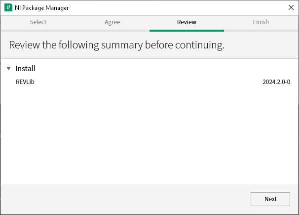
Download the latest REVLib LabVIEW package from the download link above.
Make sure LabVIEW for FRC 2026 is installed and updated.
Open the REVLib LabVIEW Package. The NI Package Manager should automatically open.
Click
You can use the online method to install REVLib C++/Java if your development machine is connected to the internet:
Open your robot project in VSCode.
Click on the WPI icon in the corner to open the WPI Command Pallet.
Select Manage Vendor Libraries.
Select Install new library (online)
Download and unzip the latest REVLib into the C:\Users\Public\wpilib\2026 directory on Windows and ~/wpilib/2026 directory on Unix-like systems.
Follow the WPILib instructions for .
Retrieving Configurations
Similar to configuration classes, devices will have a corresponding configuration accessor class. These accessor classes will contain methods to get parameters directly from the device. The structure of the accessor class resemble that of the respective configuration class where sub-configurations have corresponding nested accessors.
However, there is no need to manually instantiate a configuration accessor, as it is automatically handled by the device class. The device class has a public member object of its accessor class called configAccessor which can be used to get configuration parameters.
Below is an example of how to get a configuration parameter from a device:
Here is how to get a nested configuration parameter:
SPARK MAX vs SPARK Flex
Generally, the feature sets of the software for SPARK MAX and SPARK Flex are very similar, yet they are still very different devices and should be treated that way in code. Because of this, there are two separate device classes in REVLib: SparkMax and SparkFlex. Separating them enables better management of feature differences that currently exist or may exist later down the road.
The SPARK MAX supports using an "alternate" encoder while the SPARK Flex supports using an "external" encoder. Though these are largely similar concepts, both providing the ability to measure position and velocity external to the motor's primary encoder, the alternate encoder is limited by its inability to handle high RPM loads. Due to this caveat, separate classes exist: SparkMaxAlternateEncoder and SparkFlexExternalEncoder.
Additionally, an alternate encoder cannot be used with an absolute encoder and/or limit switches. Attempting to configure or use an alternate encoder alongside an absolute encoder/and or limit switches will throw an exception.
Closed Loop Control
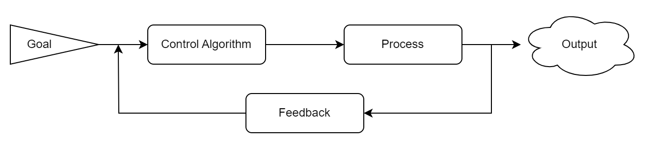
A Closed-Loop Control System in its most basic form is a process that uses feedback to improve the accuracy of its outputs. Closed-Loop Control Systems, sometimes referred to as Feedback Controllers, are frequently used when maintaining or reaching a steady output is important or if the system may have outside influences that could affect the system's output.
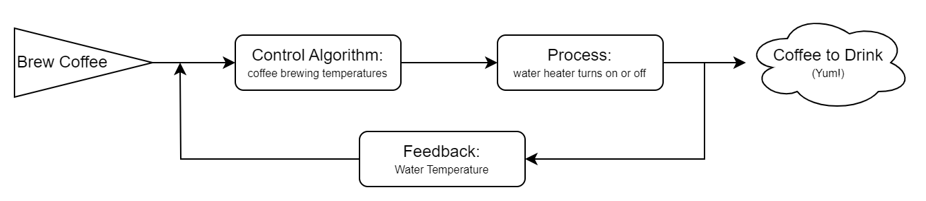
A simple example using this type of Control is an automatic coffee maker. In its Closed-Loop Control System, the output is hot coffee and the process we are getting feedback on is the heating of the water. If the coffee maker receives feedback that the water is cold, it will start to heat the pot. When the water is almost hot enough to brew the coffee, the control algorithm will continue to heat the water until the correct goal temperature has been reached. Once the water reaches it's goal temperature, or if it gets too hot, the system will stop heating the water and wait until it receives feedback that the heater needs to begin again.
Closed-Loop Control is a staple of complex FRC mechanism programming. WPILib offers to allow teams to run PID loops on the roboRIO, but they require manual setup in your team's code, need additional configuration to run at high frequencies, and may require specifically-configured feedback devices for fast responses.
Getting Started with PID Tuning
For a detailed technical and mathematical description of each term and its effect, the is a good resource.
In FRC, PID loops are used in many types of mechanisms, from flywheel shooters to vertical arms. These need to be tuned to different constants, depending on the units they use and the physical design of the mechanism, however the process to find these constants is roughly the same.
Most teams find success using controllers tuned primarily with P and D, using a Feedforward to account for
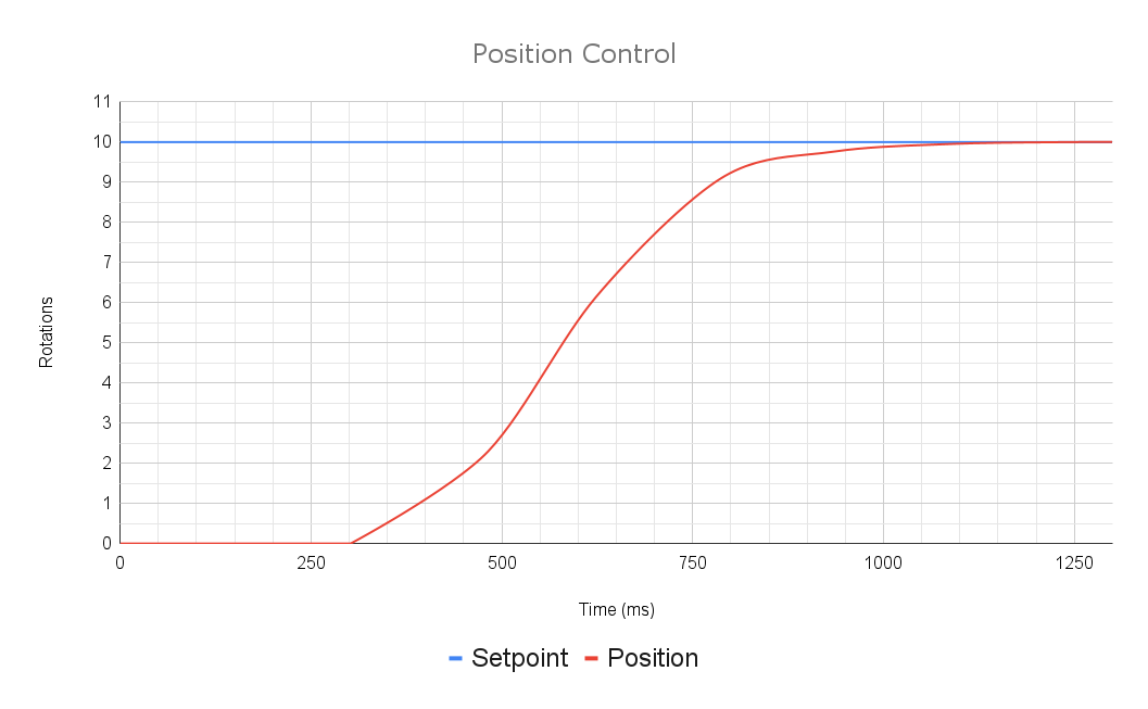
Position Control Mode
Position Control is used to point the motor in a specific direction. It takes a setpoint in rotations (or whatever unit your selected encoder's position conversion factor is in) and uses the PID loop to move to that position. The Position control mode pipes directly into a PID controller with the configured encoder.
For more complex mechanisms or motions where closer control over acceleration and velocity are needed, see
A properly tuned Position control loop should respond quickly and accurately to a setpoint change and should not oscillate around the target.
To run the motor in Position control mode, set the PID Controller setpoint as shown below.
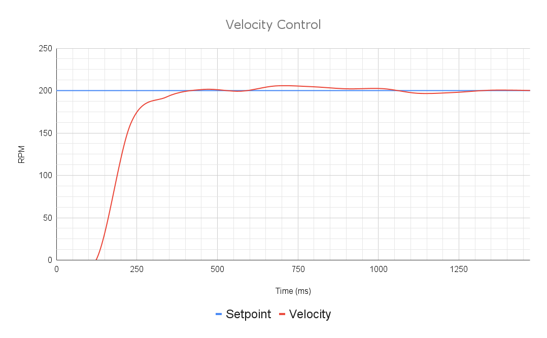
Velocity Control mode will turn your motor continuously. Be sure your mechanism does not have any hard limits for rotation.
Velocity Loop constants are often of a very low magnitude, so if your mechanism isn't behaving as expected, try decreasing your gains.
MAXMotion Velocity Control
MAXMotion Velocity Control utilizes the MAXMotion parameters to improve upon velocity control. Honoring the maximum acceleration, MAXMotion Velocity Control will speed up your flywheel or rotary mechanism in a controlled way, reducing power draw and increasing consistency.
MAXMotion Velocity Control utilizes an internal velocity closed-loop controller, so transitioning from Velocity Control mode to MAXMotion Velocity Control is as simple as setting a maximum acceleration and changing the setSetpoint call.
MAXMotion Velocity Control will turn your motor continuously. Be sure your mechanism does not have any hard limits for rotation.
Tips for Smooth Motions
The Static, Velocity, and Acceleration constants are super helpful in making your motion smooth and consistent. You should be able to get decent performance with only kV/kA and no PID at all
If your motion seems jittery, try reducing your PID constants, especially P. If the underlying velocity PID outruns the acceleration target, the motion may seem jittery and the velocity will not increase smoothly.
Make sure your units are correct: maximum velocity is set in RPM by default and maximum acceleration is set in RPM per second by default.
At low speeds, the acceleration may seem wobbly or inconsistent if the loop has been tuned for higher speeds or vice versa. If both are needed, try tuning separate PIDs and switching between slots when needed. This may be easier than finding those perfect constants that work beautifully across the board.
REVLib Simulation Feature Overview
SparkSim Features
Automatic GUI Generation
As your simulation runs, GUI elements will be added to the Devices tab as they are called, with specific dialogues for each sensor and tool.
WPILib Physics Model Integration
Every device simulation object includes a .iterate method designed for easy integration with WPILib's Physics models and tools.
Control Over Native Spark Object
Nearly every attribute of the Spark object is directly addressable via the SparkSim object, allowing you to tailor your simulations to any scenario.
Simulated Fault Manager
By creating a SimFaultManager object, you are given the ability to throw each possible fault individually, either through the GUI or programmatically with the object.
Algorithms and Features
Closed Loop Control
Position, velocity, current, MAXMotion Position Control, and MAXMotion Velocity Control algorithms have been translated into the simulation. All feedforward terms are fully supported.
MAXMotion Simulation
Both MAXMotion Position Control and MAXMotion Velocity Control are able to be fully simulated.
The Voltage Compensation algorithm from the Sparks has been ported to the simulation.
The Smart Current Limiting algorithm from the Sparks has been ported to the simulation.
All auxiliary devices are able to be fully controlled, through their individual simulation objects. Selected sensors will automatically be updated by the SparkSim.iterate() method. For more details on how to set these device simulations up, see .
Configuring a Servo Hub
This page will discuss information about configuration concepts specific to the Servo Hub. For more information on general configuration in REVLib, see .
Though Servo Hub has its own configuration class, ServoHubConfig, the majority of the configuration occurs in the ServoChannelConfig class.
For more information about what configurations and sub-configuration classes the Servo Hub provides, refer to the links below:
MAXSpline Encoder
The MAXSpline Encoder is represented by the SplineEncoder class and its parent class DetachedEncoder. This class allows the user to set the relative position. and obtain the Velocity, Relative Position, and Absolute Angle, depending on the user's needs.
Below is an example of how you construct a MAXSpline Encoder:
int parameter = device.configAccessor.getParameter1();
int parameter = device.configAccessor.subConfig1.getParameter3();
Next
:
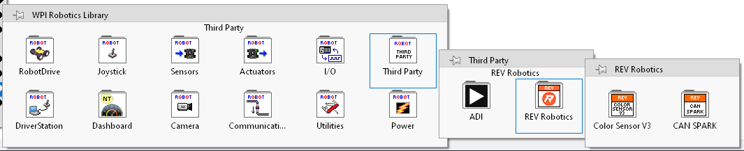
Once the installation is complete, you will be able to access the REVLib VIs at LabVIEW Functions Pallet -> WPI Robotics Library -> Third Party -> REV Robotics.
.
Enter the following installation URL and press ENTER:
The external encoder on SPARK Flex does not have these limitations. More information about the alternate encoder can be found here.
Since the majority of methods and interfaces in the two classes are largely similar, migrating between MAX and Flex can typically be done with a simple find-and-replace of class names. However, major differences listed above will need to be addressed on a case-by-case basis.
Below is a list of class names that can be interchanged between MAX and Flex:
SPARK MAX
SPARK Flex
SparkMax
SparkFlex
SparkMaxConfig
SparkFlexConfig
SparkMaxConfigAccessor
SparkFlexConfigAccessor
Below is an example of how you would migrate how a SPARK object is constructed:
SPARK MAX
SparkMax spark = new SparkMax(1, MotorType.kBrushless);
SPARK Flex
SparkFlex spark = new SparkFlex(1, MotorType.kBrushless);
SPARK MAX
using namespace rev::spark;

SparkMax m_spark{1, SparkMax::MotorType::kBrushless};
SPARK Flex
using namespace rev::spark;

SparkFlex m_spark{1, SparkFlex::MotorType::kBrushless};
It is important to ensure that the correct class is used for the device you are programming. Using the incorrect class for a SPARK motor controller will result in a warning in the driver station, and some functionalities may not work as intended.
Major Differences
Alternate vs External Encoder
Migrating between MAX and Flex in REVLib
With a PID loop onboard a SPARK Motor Controller, the setup is simple, doesn't clutter your code, and the loop is updated every 1ms, increasing the responsiveness and precision of the controller. Even when using a more complex control algorithm on the roboRIO, it's still recommended to put as much processing on the motor controller as possible. The PID controller onboard the SPARK can also be configured and tuned with the REV Hardware Client, allowing for a much faster tuning process that doesn't rely on your other subsystems.
Configuring SPARK PID with REVLib can be done in a couple of lines and fits right into the configuration of the motor controller.
Setting a setpoint for the PID is just as easy, whether you want to set a position or velocity or even use a motion profile.
Both the SPARK MAX and SPARK Flex can operate in several closed-loop control modes, using sensor input to tightly control the motor velocity, position, or current. The internal control loop follows a standard PID algorithm and incorporates several feedforward terms to account for known system dynamics. This allows the motor to follow precise and repeatable motions, useful for complex mechanisms.
Additionally, an arbitrary feedforward signal is added to the output of the control loop after all calculations are done. The units for this signal can be selected as either voltage or duty cycle. This feature allows more advanced feedforward calculations to be performed by the controller. This can be useful for systems with more complex dynamics than can be represented by the SPARK feedforward.
P, the proportional gain, is the primary factor of the control loop. This is multiplied by the error and that gain is added to the output. This does the heavy lifting of the motion, pushing the motor in the direction it needs to go.
I, the integral gain, is not often recommended in FRC. It is useful for eliminating steady-state error, or error that the other gains leave behind and cannot address. It accumulates the error over time and multiplies it by the I gain, gradually increasing the power it supplies until that has evened out. If it is needed, it's recommended to use a limited to prevent I windup. For FRC purposes, Feedforward gains are recommended to eliminate steady-state error instead.
The derivative gain, D, is used to tune out oscillation and dampen the motion. It resists motion, decreasing power when the mechanism is moving. A good balance of P and D is needed to make a smooth motion with no oscillation.
Several guides for PID tuning are available, such as this technical one on the WPILib docs. It may be useful to consult multiple, especially those available that reference your specific mechanism.
Any method for PID tuning will start with the same concept, however, regardless of mechanism. Before you can tune your mechanism, you should setup a graph of the setpoint and that measured value, either through the REV Hardware Client or a similar utility. This will allow you to analyze each test and properly evaluate the changes to make.
To then tune a basic PID loop, follow the steps below:
Set all constants (P, I, D, etc) to 0
Ensure the mechanism is safe to actuate. This process will spin the motor, potentially at unexpected speeds and in unexpected directions
Check the direction of the motor, and invert it if needed so that positive output is in the desired direction
Set P to a very small number, relative to the units you are working in
Set a target for the motor to move to. Ensure this is within the range of your mechanism.
Gradually increase P until you see movement, by small increments
Once you see motion, increase P by small increments until it reaches the target at the desired speed
If you see oscillation, decrease P or begin to increment D by a small amount. A precisely tuned P gain is better than a D gain, but a D gain may be needed to counteract the dynamics of the system
Continue to adjust these parameters until the motion is quick, precise, and repeatable
Configuring a Servo Hub automatically persists the configuration settings between power cycles when calling the configure() method.
Persisting parameters involves saving them to the Servo Hub's memory, which is time-intensive and blocks communication with the device.
It is recommended to update the majority of device parameters during the initial configuration of the device at the start of your program to ensure that the controller retains its configuration in the event of a power cycle during operation, e.g., due to a breaker trip or a brownout.
It is generally recommended not to make updates to the configuration mid-operation to avoid blocking the program and affecting the performance of the robot.
Simulating Additional Sensors and Auxiliary Devices
Each Spark device has a set of additional sensors, limit switches, and encoders that can be accessed and addressed in your robot code. To simulate each of these, we use a similar model where the user can directly set, either via the GUI or programmatically, each value that these devices measure.
As each auxiliary device is addressed in your native robot code they will be added to the simulation GUI, allowing you to easily adjust their values and test a variety of scenarios.
For example, the code below will generate the GUI display shown below:
SparkMaxm_motor=newSparkMax(10
usingnamespacerev::spark;
Simulating Auxiliary Devices in Code
In the same fashion as the Spark devices, all auxiliary devices have their own Sim classes for accessing the simulation tooling. These follow a similar model, where all physics and motion or change in sensor values need to be handled externally, allowing you to configure these auxiliary devices in the simulation to match how they behave on your robot.
Each Encoder Sim class also contains a .iterate function, which automatically updates both position and velocity from a velocity input, streamlining the process of integrating with an existing WPILib physics simulation. For example, an External/Alternate Encoder attached after a gearbox could be updated with the motor's velocity transformed by the gear ratio to provide accurate measurements, or an independent simulation could be run for the auxiliary device.
Simulation
Simulation Basics
Testing is an important part of building solid software, and programming robots is no different. When writing code for an FRC robot, testing often involves a fully assembled robot and dedicated time for the Programming team to experiment on it, both of which can be hard to come by at times. When time with the robot is valuable, it's important that your code works how you expect it to on the first try. That's where simulation comes in.
Simulating your robot code allows you to control every input and view every output of your robot code in a simulated environment, letting you put your "robot" in scenarios to see that it does what you want. A simple usage might be to make sure your controls aren't inverted, and a more complicated application may be physics simulating an entire autonomous routine or running automated unit tests on every build. With (quite a lot of) work, you could even practice driving entire matches before the robot is even built.
The basic flow of the simulation is shown in the diagram below, where your code does its thing and all the simulation magic can happen behind the scenes. Your inputs and setup on the GUI are fed right to your code as if the robot was actually there, allowing you to test simple systems without adding anything at all. To test more complicated systems or run physics simulations, you can add some simulation specific code to address the simulation directly and allow you to further customize your control over the simulation.
Simulation is something that can help every team, from the first-time programmers who want to make sure something works as expected to the high-level teams who want to run physics simulations and test complicated algorithms. The more work you put into developing your simulations, the more complex and detailed they can become. That being said, getting started is simple and you can see immediate results with little to no code.
Using a DetachedEncoder as a SPARK's feedback sensor
A DetachedEncoder, such as the MAXSpline Encoder, may be used as a FeedbackSensor for Closed Loop Control in SPARK MAX and SPARK Flex motor controllers.
This is configured in the ClosedLoopConfig class using the feedbackSensor(FeedbackSensor, int) or feedbackSensor(FeedbackSensor, DetachedEncoder) methods as follows:
SplineEncoderspline=newSplineEncoder(12
usingnamespacerev::detached;
Units
Quantity
Default Units
Affected by
Configuring Devices
Starting 2025, REVLib shifted its device configuration paradigm towards something more declarative. This approach promotes better code organization and readability while also reducing boilerplate code. Additionally, it opens the door for enhanced configuration validation as well as reusability of code, aligning with principles of good object-oriented design.
This page explores how different parts of REVLib's configuration paradigm works and how you can use it effectively in your robot program. For more information on device specific configurations, see the following:
In this configuration paradigm, each device has its own dedicated configuration class which serves as a structure for organizing and storing the parameters to be configured for that device.
All parameters in a configuration are optional
Flexibility with Configurations
Because configuration objects are not tied to a single device, they can be used multiples times for multiple devices of the same type, reducing the amount of boilerplate code for devices that function similarly.
Configuration classes provide an apply() method to apply parameters from one configuration to another, providing greater flexibility when configuring multiple devices of the same type.
For example, you can create a common configuration for multiple devices of the same type and apply it to each device's individual configuration. This simplifies setup by avoiding duplicated code, allowing you to focus on setting only the unique parameters for each device.
Depending on the configuration class, multiple overloaded apply() methods may be provided. However, the simplest form of apply() accepts a configuration object of the same type as the target. Just like the other parameter setting methods, apply()
Configuring a SPARK
This page will discuss information about configuration concepts specific to only SPARK MAX and SPARK Flex. For more information on general configuration in REVLib, see .
SPARK MAX and SPARK Flex each have their own configuration classes, SparkMaxConfig and SparkFlexConfig. They are both derived from SparkBaseConfig which includes shared configurations between the two devices. Configurations specific to SPARK MAX or SPARK Flex live in their respective configuration class.
For more information about what configurations and sub-configuration classes each class provides, refer to the links below:
Configuring a DetachedEncoder
This page discusses configuration concepts specific to DetachedEncoders, such as the MAXSpline Encoder. For more information on general configuration in REVLib, see .
The MAXSpine Encoder uses a common configuration class, DetachedEncoderConfig.
For more information about what configurations and sub-configuration classes each class provides, refer to the links below:
returns a modified instance of the object for method chaining.
Importantly, applying a configuration is distinct from copying it. Copying would completely overwrite the target configuration, including potentially removing parameters previously set. Instead, apply() selectively updates parameters.
The apply() method updates only the parameters that exist in the passed configuration object. Parameters in the target configuration that are not present in the passed configuration remain unchanged. If a parameter exists in both the target and the passed configurations, the value from the passed configuration takes precedence.
Below is a basic example of how apply() can be used to create a starting point from another configuration:
You can also adjust parameters that were set from calling apply():
Calling apply() may override previously set parameters, so it is important to keep ordering in consideration:
For configuration classes that contain sub-configurations, using the base apply() will also apply the parameters from the passed object's sub-configurations to the target's. The same will apply to further nested sub-configurations.
Configuration classes that contain sub-configurations will also provide overloaded methods of apply() for each of its sub-configurations. These methods allow you to apply a sub-configuration object to multiple parent configurations.
Config config1 = new Config();
Config config2 = new Config();

config1
    .parameter1(42)
    .parameter2(43);

config2
    .apply(config1)
    .parameter3(44);

/*
 * config1 will have the values:
 *   parameter1: 42
 *   parameter2: 43
 *
 * config2 will have the following values:
 *   parameter1: 42
 *   parameter2: 43
 *   parameter3: 44
 */
Config config1 = new Config();
Config config2 = new Config();

config1
    .parameter1(42)
    .parameter2(43);

config2
    .apply(config1)
    .parameter2(44);

/*
 * config1 will have the values:
 *   parameter1: 42
 *   parameter2: 43
 *
 * config2 will have the following values:
 *   parameter1: 42
 *   parameter2: 44
 */
Config config1 = new Config();
Config config2 = new Config();

config1
    .parameter1(42)
    .parameter2(43);

config2
    .parameter2(44)
    .apply(config1);

/*
 * config1 will have the values:
 *   parameter1: 42
 *   parameter2: 43
 *
 * config2 will have the following values:
 *   parameter1: 42
 *   parameter2: 43
 */
Config config1 = new Config();
Config config2 = new Config();

config1
    .parameter1(42)
    .parameter2(43)
    .subConfig1
        .parameter3(44);

config2.apply(config1);

// config2's subConfig1 will have parameter3 set to 44
Config config1 = new Config();
Config config2 = new Config();
SubConfig1 subConfig1 = new SubConfig1();

config1
    .parameter1(42)
    .parameter2(43)
    .subConfig1
        .parameter3(44);

subConfig1
    .parameter3(45);

config2
    .apply(config1)      // base apply(Config)
    .apply(subConfig1);  // overloaded apply(SubConfig1)

// config2's subConfig1 will have parameter3 set to 45
Position Conversion Factor
Encoder Velocity
RPM
Velocity Conversion Factor
Applied Output
Duty Cycle
kP
Duty cycle per rotation
Position Conversion Factor
kI
Duty cycle per (rotation*ms)
Position Conversion Factor
kD
(Duty cycle*ms) per rotation
Position Conversion Factor
kS
Volts
kV
Volts per RPM
Velocity Conversion Factor
kA
Volts per RPM/s
Velocity Conversion Factor
kG
Volts
kCos
Volts per Rotation
MAXMotion Cruise Velocity
RPM
Velocity Conversion Factor
MAXMotion Maximum Acceleration
RPM/s
Velocity Conversion Factor
MAXMotion Allowed Profile Error
Rotations
Position Conversion Factor
There are two configurable Conversion Factors on each Encoder type that can be used to account for gear ratios and unit conversions in the motor control logic. These are applied independently and the velocity factor does not rely on the position factor, so different units can be used for each.
Positions read from the feedback encoder are multiplied by the Position Conversion Factor before being processed by the closed-loop controller.
Description
Factor
Default (Revolutions)
1
Degrees
360
Radians
2π (6.28318530718)
Velocities read from the feedback encoder are multiplied by the Velocity Conversion Factor before being processed by the closed-loop controller.
The velocity conversion factor is completely independent of the position conversion factor, so both need to be set to change both units.
All accelerations on the SPARK controllers are in terms of velocity per second, where the velocity is in units specified by the Velocity Conversion Factor.
Description
Factor
Default (RPM)
1
Revolutions per Second
1/60 (0.01666666666)
Degrees per Minute
360
Setpoint
Rotations
Position Conversion Factor
Encoder Position
Default Units
Rotations
Conversion Factors
Position Conversion Factor
Common Position Conversion Factors
Velocity Conversion Factor
Common Velocity Conversion Factors
, meaning all parameters will remain unchanged unless otherwise specified. This minimizes the traffic between REVLib and the device when applying the configuration.
As a result, configuration classes are not intended to represent the device's complete configuration—though this is possible, it is generally unnecessary. Their primary purpose is to set only the parameters that are relevant to your needs.
For details on retrieving parameters from a device, refer to this section.
Configuration parameters can be set via methods on a config object, and those methods return a modified instance of the object, allowing you to perform method chaining for more organized and readable code.
Below is an example of how you would set parameters using method chaining:
Config classes can also contain sub-configs as members of the class, allowing for improved organization by grouping conceptually-related configuration parameters together. Since a sub-config is its own configuration class, its methods return the sub-config instead of its parent. To configure something outside the sub-config, you'll need to start a new chain of method calls.
Additionally, a sub-config can have its own sub-configs, allowing parameters to be deeply nested within the hierarchy.
Applying the concepts described above, this is how an example configuration class would be composed.
An example configuration class
After setting up your configuration object, you can apply the configuration by calling the configure() method on your device object.
The method signature may differ between devices, so be sure to consult the device's configuration documentation. In all cases, however, configure() takes a configuration object and a ResetMode value as arguments and returns a REVLibError.
The ResetMode argument specifies whether to reset the parameters before applying the configuration. This argument is required to ensure the user makes the conscious decision whether to reset the parameters, helping to avoid potential pitfalls.
Resetting parameters before applying a new configuration ensures the device starts in a known, good state. This is particularly useful when initializing the device at the start of a program, and by starting with a clean slate, you can guarantee the configuration is consistent each time the robot powers up. This approach is especially valuable when performing a drop-in replacement for a device, as the replacement may be in an unknown state.
A reason to not reset parameters when applying a configuration is to preserve previously set values during a mid-operation adjustment. While reconfiguring a device during operation is generally discouraged, some use cases may necessitate it.
Another reason to not reset parameters is when you are using the REV Hardware Client as your primary configuration tool. Although configuring devices through code is considered a best practice, the Hardware Client remains a valid and supported option for configuration.
Below is an example of either case:
This only applies to Java and C++.
Overview
Color Sensor V3 does not follow the device configuration paradigm described on this page.
public Robot() {
    Config initialConfig = new Config();
    initialConfig
        .parameter1(42)
        .parameter2(43)
        .parameter3(44);

    // Reset parameters for consistent initialization
    device.configure(initialConfig, ResetMode.kResetParameters);
}

void updateConfig() {
    Config updatedConfig = new Config();
    updatedConfig.parameter3(45);

    // Don't reset parameters since we only want to change one parameter
    device.configure(updatedConfig, ResetMode.kNoResetParameters);
}
Setting Parameters
Sub-configs
Example Configuration Class
Applying a Configuration to Your Device
Resetting Parameters Before Configuring
Use Cases
SparkMaxConfig
SparkFlexConfig
SparkBaseConfig
Configuring a SPARK MAX and SPARK Flex differs from other devices in REVLib with the addition of the persistMode parameter in their configure() methods, which specifies whether the configuration settings applied to the device should be persisted between power cycles.
Persisting parameters involves saving them to the SPARK controller's memory, which is time-intensive and blocks communication with the device. To provide flexibility, this process is not automatic, as this behavior may be unnecessary or undesirable in some cases. Therefore, users must manually specify the persist mode, and to help avoid possible pitfalls, it is a required parameter.
It is recommended to persist parameters during the initial configuration of the device at the start of your program to ensure that the controller retains its configuration in the event of a power cycle during operation e.g. due to a breaker trip or a brownout.
When making updates to the configuration mid-operation, it is generally recommend to not persist the applied configuration changes to avoid blocking the program, depending on the use case. While reconfiguring a device during operation is generally discouraged, some use cases may necessitate it, and it is important to make the choice whether to persist parameters as it can affect performance of the robot.
Below is an example of either case:
Robot() {
    SparkMaxConfig config = new SparkMaxConfig();
    config
        .smartCurrentLimit(50)
        .idleMode(IdleMode.kBrake);

    // Persist parameters to retain configuration in the event of a power cycle
    spark.configure(config, ResetMode.kResetSafeParameters, PersistMode.kPersistParameters);
}

void setCoastMode() {
    SparkMaxConfig config = new SparkMaxConfig();
    config.idleMode(IdleMode.kCoast);

    // Don't persist parameters since it takes time and this change is temporary
    spark.configure(config, ResetMode.kNoResetSafeParameters, PersistMode.kNoPersistParameters);
}
Motor type is the only configuration parameter that must be set outside of a configuration object, specifically through the constructor of the SparkMax and SparkFlex classes. This ensures that the user makes the conscious decision the specify type of motor is being driven, as driving a brushless motor in brushed mode can permanently damage the motor.
Below is an example of how configuring for different motor types would look like:
SparkMax neo = new SparkMax(1, MotorType.kBrushless);
SparkMax cim = new SparkMax(2, MotorType.kBrushed);

SparkMaxConfig cimConfig = new SparkMaxConfig();

// Configure primary encoder for brushed motor
cimConfig.encoder
    .countsPerRevolution(8192)
    .inverted(true);

cim.configure(cimConfig, ResetMode.kResetSafeParameters, PersistMode.kPersistParameters);
Configuring a DetachedEncoder automatically persists the configuration settings between power cycles when calling the configure() method.
Persisting parameters involves saving them to the device's memory, which is time-intensive and blocks communication with the device.
It is recommended to update the majority of device parameters during the initial configuration of the device at the start of your program to ensure that the controller retains its configuration in the event of a power cycle during operation, e.g., due to a breaker trip or a brownout.
It is generally recommended not to make configuration updates mid-operation to avoid blocking the program and affecting the robot's performance.
Introduced in 2026, Status Logger serves as the official solution to logging CAN status frames for REV devices. Previously, the third-party library, Unofficial REV-Compatible Logger (URCL), was the only solution for logging raw CAN data for REV devices, but Status Logger brings the core logging functionality natively to REVLib.
URCL still has its benefits over Status Logger, but the main benefit of Status Logger is that it is enabled by default and requires no setup. This is especially useful for a CSA diagnosing a problem with a team that may not have had the foresight to setup logging.
Status Logger supports the following devices:
SPARK Flex
SPARK MAX
Servo Hub
MAXSpline Encoder
The code docs for Java and C++ are available below:
Status Logger will automatically log .revlog files to the roboRIO internal storage if no USB drive is attached. It is recommended to insert an external USB drive for storing .revlog files to reduce clutter on the roboRIO. Any inserted USB drive will be automatically logged to after it is initially plugged in and power cycled.
Status Logger is enabled by default on the first invocation of any REVLib device object, thus requiring no user setup for default behavior.
If desired, call the disableAutoLogging() static method to disable automatic logging. This method must be called before any other REVLib function is invoked. The recommended placement is as the first line in your robotInit() method. After calling this, logging will not occur until it is explicitly started with start(). This is useful for applications that require full manual control over the logging lifecycle.
With automatic logging disabled, the start() and stop() static methods can be called to start and stop writing data to the .revlog file when desired. An example use case could be calling start() at the beginning of autonomousInit() or teleopInit() and calling stop() at the beginning of disabledInit(). To avoid any expected behaviors, it is recommended to call disableAutoLogging() as described above before implementing manual logging.
To prevent overflowing the logging storage device, Status Logger has the following safeguards in place:
When the log storage device has less than 100 MB of free space remaining, StatusLogger sends a warning message to consider deleting old .revlog files off of the storage device.
When the log storage device has less than 50 MB of free space remaining, the oldest .revlog files in the log storage device are automatically deleted until the free space available is greater than 50 MB.
Each .revlog file is named by start timestamp in the format: REV_<Year><Month><Day>_<Hour><Minute><Second>.revlog After logging, there are two ways of retrieving the .revlog file depending on your robot setup.
If there is no USB drive plugged into the roboRIO, files can be retrieved via FTP. See on roboRIO FTP. The .revlog files are logged to "/home/lvuser/logs/" on the roboRIO.
If there is a USB drive plugged into the roboRIO, files can be retrieved from the "/u/logs/" directory with the flash drive plugged in. Alternatively, the flash drive can be simply unplugged and inserted into any device to access the .revlog files.
.revlog files are not viewable in typical FRC log viewing tools and must first be converted to a .wpilog, where the raw CAN data of the .revlog is parsed into individual timestamped signals.
The recommended and easiest way is to open .revlog files directly in , where they are automatically converted to .wpilog files. See the for more information.
The second option is to use the . The NPM package allows you to integrated the converter into any node project while also enabling you to run it as a command line tool if installed globally. See the package documentation for more information.
Simulation Getting Started
WPILib Simulation Tools
In WPILib VSCode, running a robot code simulation is easy: click the WPILib icon in the top right corner of the UI and select 'Simulate Robot Code'. This will compile your code and launch the Simulation GUI, which displays controls and data during your simulation.
You may be prompted to enable Desktop support for your project, especially if you are using C++, or you may need to manually enable it if features don't work as expected. This can be changed by clicking the WPILib logo and selecting 'Change Desktop Support Enabled Setting'.
The Simulation GUI
Once your simulation is running, you'll be prompted to use the Simulation GUI or the normal driver station for simulation control. The Sim GUI has many helpful interfaces all in one place, like the NetworkTables GUI and Other Devices display, so that's what we'll cover here.
To access the Other Devices display, shown on the right, open it via Hardware > Other Devices at the top of the screen. These drop down interfaces are generated by your code and will contain the list of applicable devices, without any simulation-specific code needed.
The GUI in the center contains the NetworkTables, the one at the top left controls enable/disable state, and the one at the bottom left controls joystick order. These give you basic control over the simulation and how you want to interface with it and outputs like you'd see during a match. You can even use a keyboard to emulate a controller if you don't have one! For more information on other elements, .
Without any simulation-specific code, your Spark devices will still offer some simulation features. Parameters and settings will be able to be set and retrieved, the setpoint and control mode can be set, and the simulation GUI will reflect all of these changes. However, additional code is required to update the applied output or position/velocity and to access the more complex features of the simulation.
As shown below, both the Spark Flex and Spark MAX have Sim classes, which give you full control over the devices and give you access to the methods needed to update the output of the simulated motor controllers.
With these Spark sim objects, you can read and write many fields within the simulation, like manually setting the position, velocity, or motor temperature. The values you set will be visible in the sim GUI and will also be returned by the native functions to get these values in your robot code.
These Spark sim objects also have a method, called .iterate, that will simulate many of the features of the motor controller and allow you to simulate the motion of the motor with the help of a WPILib physics simulation.
. These will help us simulate the motion of a motor, as they handle the underlying physics of the load of the motor. Selecting a model and filling out the appropriate fields to describe your physical system will make the simulation as close to real life as possible. These values can be calculated from a CAD model, or measured on a robot.
During a simulation, the physics model takes in the voltage applied to the motor and returns the velocity with which the motor is rotating. The Spark sim's .iterate method takes in the velocity of the motor from the physics model, the bus voltage (supply voltage to the controller), and the time interval for calculations (0.02 seconds, unless you want to track time differently), and updates all the fields of the Spark sim and native Spark to reflect the new state. An example with a simulated arm and a Spark Flex is shown below, but the Spark MAX behavior is the same and the Arm system could be substituted for another WPILib model.
To see the full list of features, check out
To simulate sensors and auxiliary devices, see
Commanding Servos
Servo motors are specialized motors that can be controlled to move to a specific angle instead of continuously rotating like a DC motor. For more general information on servos, see ; for more detailed information, see .
Servo control in REVLib is accessed through the ServoHub's object. This object manages the individual ServoChannel objects and monitors the overall device. The ServoChannel object controls each servo motor and monitors its operation. It also contains all the methods to configure and control your servo. It can be accessed as shown below:
API Docs: ,
API Docs: ,
With a servo motor, the width of the pulse will determine how far the motor turns. The Pulse Period, on the other hand, will determine how often the pulse is sent to the servo. The ServoHub supports a Pulse Period of 4.5 - 20ms (specified in microseconds). The ServoHub supports a separate Pulse Period for each bank, composing servos 0-2 and 3-5, respectively. These settings can be accessed as shown below:
10:1 Gearbox, Rotations at output
1/10 (0.1)
Distance in inches traveled with a 6in diameter wheel
When the log storage device has less than 5 MB of free space remaining, logging is stopped automatically. Deleting .revlog files can be done by accessing the file storage device through the methods described below and simply deleting the files to free up space.
// create the DCMotor objects to specify the motor type
DCMotor maxGearbox = DCMotor.getNEO(1);
// multiple motors attached to the same gearbox in follower mode should be
// simulated as one motor
DCMotor flexGearbox = DCMotor.getNeoVortex(2);

// create the normal Spark MAX object
SparkMax max = new SparkMAX(10, MotorType.kBrushless);
// create the Spark MAX sim object
SparkMaxSim maxSim = new SparkMaxSim(max, maxGearbox);

// create the normal Spark Flex object
SparkFlex flex = new SparkFlex(11, MotorType.kBrushless);
// create the Spark Flex sim object
SparkFlexSim flexSim = new SparkFlexSim(flex, flexGearbox);
using namespace frc;
using namespace rev::spark;

// create the DCMotor objects to specify the motor type
DCMotor maxGearbox = DCMotor::NEO(1);
// multiple motors attached to the same gearbox in follower mode should be
// simulated as one motor
DCMotor flexGearbox = DCMotor::NeoVortex(2);

// create the normal Spark MAX object
SparkMax max{10, SparkMax::MotorType::kBrushless};
// create the Spark MAX sim object
SparkMaxSim maxSim{&max, &maxGearbox};

// create the normal Spark Flex object
SparkFlex flex{11, SparkFlex::MotorType::kBrushless};
// create the Spark Flex sim object
SparkFlexSim flexSim{&flex, &flexGearbox};
public void simulationPeriodic() {
    // In this method, we update our simulation of what our arm is doing
    // First, we set our "inputs" (voltages)
    m_armSim.setInput(m_motorSim.getAppliedOutput() * RoboRioSim.getVInVoltage());

    // Next, we update it. The standard loop time is 20ms.
    m_armSim.update(0.02);

    // Now, we update the Spark Flex
    flexSim.iterate(
        Units.radiansPerSecondToRotationsPerMinute( // motor velocity, in RPM
            m_armSim.getVelocityRadPerSec()),
        RoboRioSim.getVInVoltage(), // Simulated battery voltage, in Volts
        0.02); // Time interval, in Seconds

    // SimBattery estimates loaded battery voltages
    // This should include all motors being simulated
    RoboRioSim.setVInVoltage(
        BatterySim.calculateDefaultBatteryLoadedVoltage(m_armSim.getCurrentDrawAmps()));

    // Update any external GUI displays or values as desired
    // For example, a Mechanism2d Arm based on the simulated arm angle
    m_arm.setAngle(Units.radiansToDegrees(m_armSim.getAngleRads()));
}
using namespace frc;

void Arm::SimulationPeriodic() {
    // In this method, we update our simulation of what our arm is doing
    // First, we set our "inputs" (voltages)
    m_armSim.SetInput(
        Vectord<1>{flexSim.getAppliedOutput() * RobotController::GetInputVoltage()});

    // Next, we update it. The standard loop time is 20ms.
    m_armSim.update(0.020);

    // Now, we update the Spark Flex
    flexSim.iterate(
        units::revolutions_per_minute_t( // motor velocity, in RPM
            m_armSim.getVelocity()).to<double>(),
        RoboRioSim.getVInVoltage(), // Simulated battery voltage, in Volts
        0.02); // Time interval, in Seconds

    // SimBattery estimates loaded battery voltages
    // This should include all motors being simulated
    sim::RoboRioSim::SetVInVoltage(
        sim::BatterySim::Calculate({m_armSim.GetCurrentDraw()}));

    // Update any external GUI displays or values as desired
    // For example, a Mechanism2d Arm based on the simulated arm angle
    m_arm->SetAngle(m_armSim.GetAngle());
}
// Set the pulse period for channels 0-2 to 5ms (5000 microseconds)m_servoHub.setBankPulsePeriod(ServoHub
Individual servos are controlled via the ServoChannel objects. As shown above, you obtain a reference to a ServoChannel object by calling the getServoChannel() method on the ServoHub. You may set the following on a ServoChannel:
PulseWidth - determines the servo's position (500 - 2500 microseconds).
Enabled - enables/disables the servo - when disabled, the servo will maintain power according to the DisableBehavior configured for the specific channel.
Powered - turns on/off the power to the servo
// Power on channels 0, 1, and 4
m_channel0.setPowered(true);
m_channel1.setPowered(true);
m_channel4.setPowered(true);

// Enabled them as well
m_channel0.setEnabled(true);
m_channel1.setEnabled(true);
m_channel4.setEnabled(true)

// Set the servo on channel 0 to the center (1500 microseconds)
m_channel0.setPulseWidth(1500);

// Set the servo on channel 1 to the far left (500 microseconds)
m_channel1.setPulseWidth(500);

// Set the servo on channel 4 to the far right(2500 microseconds)
m_channel4.setPulseWidth(2500);
using namespace rev::servohub;

// Power on channels 0, 1, and 4
m_channel0.SetPowered(true);
m_channel1.SetPowered(true);
m_channel4.SetPowered(true);

// Enabled them as well
m_channel0.SetEnabled(true);
m_channel1.SetEnabled(true);
m_channel4.SetEnabled(true)

// Set the servo on channel 0 to the center (1500 microseconds)
m_channel0.SetPulseWidth(1500);

// Set the servo on channel 1 to the far left (500 microseconds)
m_channel1.SetPulseWidth(500);

// Set the servo on channel 4 to the far right(2500 microseconds)
m_channel4.SetPulseWidth(2500);
// Initialize the servo hubServoHubm_servoHub=newServoHub(deviceID);// Obtain a servo channel controllerServoChannelm_channel0=m_servoHub.getServoChannel(ChannelId.kChannelId0);ServoChannelm_channel1=m_servoHub.getServoChannel(ChannelId.kChannelId1);...ServoChannelm_channel5=m_servoHub.getServoChannel(ChannelId.kChannelId5);
usingnamespacerev::servohub;usingnamespacerev::servohub::ServoChannel;// Initialize the servo hubServoHub m_servoHub{ deviceID };//Obtain a reference to a servo channel controllerServoChannel& m_channel0 =m_servoHub.GetServoChannel(ChannelId.kChannelId0);ServoChannel& m_channel1 =m_servoHub.GetServoChannel(ChannelId.kChannelId1);...ServoChannel& m_channel5 =m_servoHub.GetServoChannel(ChannelId.kChannelId5);
Controlling an Individual Servo
MAXMotion Position Control
MAXMotion Position Control is a second-degree closed loop controller, allowing for smooth and consistent motions from one position to another by limiting both the velocity and acceleration of the motor. These can be configured via the , setting a target acceleration and a "cruise" velocity. The motor will spin up, honoring the acceleration target, hold speed at the cruise velocity, and then slow down honoring the acceleration target to arrive at the setpoint. MAXMotion updates its motion profile every 10ms and the underlying PID controller every 1ms, which makes it extremely fast and responsive.
MAXMotion generates a profile containing all the key transition points between the current position and the setpoint and uses that to calculate intermediate positions for the PID controller to follow.
Each point along the profile is a target for the PID controller at the point in time it corresponds to. If, at some point in time, the actual measured position is more than the configured Allowed Profile Error away from the profile, the profile will be regenerated from the current position and velocity. While the mechanism is within that margin, it will continue to track the same profile. This makes tuning easy and makes motions consistent and accurate.
The SPARK Feedforward system was designed with MAXMotion in mind, and MAXMotion can take advantage of all of its features.
.
Bank
.
kBank0_2
,
5000
);
// Set the pulse period for channels 3-5 to 20ms (20000 microseconds)
The first step of setting up MAXMotion is to configure the PID feedforwards, as explained on the feedforward page. The kV and kA values from a calculator, converted to appropriate units, or from a tool like SysID are perfect starting points for tuning.
There are 3 primary constants to configure for MAXMotion:
Cruise Velocity: this is the speed you want the motion to hold through the middle of its path
Maximum Acceleration: this is the acceleration you want to use to speed up and slow down the motion
Allowed Profile Error: this is the amount of position deviation from the profile that is allowed before the profile is regenerated
Constant
Associated behavior
Cruise Velocity
This is the top of the trapezoid, the velocity that is sustained through the center stage of the motion. Increasing it beyond what is achievable will result in a triangular "trapezoid" on you Velocity graph.
Maximum Acceleration
This is how quickly the mechanism accelerates. Increasing it too much will draw a lot of current, and may hit the current limits or stall the motors.
Allowed Profile Error
This is how "loose" the profile is, and how far your mechanism can get from the profile before the profile is regenerated. For tuning, it's helpful to set this to a large value so you can see the behavior without the profile resetting, but the end goal for your motion should be to minimize this margin.
Ensure the mechanism is free to move and note any mechanical limits
Set up the Feedforwards for the mechanism. Note that these may not provide expected results until other values are setup
Set P to a very small number, relative to your position units. For the default units, kP = 0.01 is a good starting point. Keep in mind that kP will be multiplied by your position error and then become duty cycle percent output, so pick a "small" value relative to what your position error is expected to be
Set the Cruise Velocity and Max Acceleration to small numbers, relative to your velocity units and gear ratio. For a directly-driven mechanism with default units, 30 RPM and 10 RPM/s respectively are good starting points to see the effects of MAXMotion and clearly see the impacts of each parameter, but these are very slow and will need increased
Set the Allowed Profile Error to a high number relative to your units and the distance to your setpoint. For most motions at the default units, an Allowed Profile Error of 1 Rotation is enough to get started. If the results are confusing, especially if the acceleration targets appear to be too low, increase this. Increasing this value will let the motion continue for a longer period before regenerating the profile, which may uncover the root of a tuning issue
Set up a method to retrieve relevant info
If running a robot program, use NetworkTables to post this information
Several of these values can be fetched from the SparkClosedLoopController object
Tuning for your mechanism using is a safe, good way to start, but will probably still need further tweaking to make the actual mechanism's motion perfect
Be very careful, as this tuning process could cause your mechanism to move in unpredictable or unexpected ways if the constants are off, particularly if your units don't match up
Repeat the following process until the results are satisfactory
Run and record a motion to a known setpoint
If the motion is jittery or shaky, reduce kP. If your Allowed Profile Error is small, increase it to a large number while diagnosing issues
A well-tuned MAXMotion controller will:
Track position, velocity, and acceleration closely and accurately
Respond quickly to a change in setpoint
Not stutter or reset
Move smoothly and in a controllable way
Move quickly
Not overshoot the setpoint
The acceleration will be set as high as is smooth without hitting the current limit
The velocity will be set as high as is achievable and smooth
The allowed profile error will be as small as possible
After tuning your constants, calling MAXMotion is as simple as passing in the setpoint to the controller.
Smart Motion used a different method for smooth second-degree motion control, but MAXMotion can be applied anywhere Smart Motion was previously. Maximum velocity and acceleration constants may be transferable, but should be tested with caution. All other constants will need re-tuned from scratch, including all PIDs.
MAXMotion has several improvements over Smart Motion, and should offer better consistency, a better tuning experience, better position retention, and an all-around better user experience. It is highly recommended to migrate all systems using Smart Motion to MAXMotion.
If changes to quantities aren't showing the expected results, the Current Limits may be engaging. This will limit the acceleration of the system and can be remedied by increasing the Current Limit (within reason) or increasing the Gear Ratio.
What do the constants do?
Tuning for MAXMotion Position Control
What does "good tuning" look like?
Using MAXMotion
Migrating from Smart Motion
As Smart Motion and MAXMotion Position Control use different underlying control methods, all PID constants will need to be re-tuned from scratch.
A dashboard like Glass or AdvantageScope can help graph and record these values
In the REV Hardware Client, use the Telemetry tab to enable this information
Good information to watch while tuning:
Position
Velocity
Applied Output
MAXMotion Position Setpoint
MAXMotion Velocity Setpoint
Setpoint
Current Draw
Note that fetching all these values may require modifying the Status Frame Periods for certain parameters as the CAN bus or the SPARK device reaches its limit. If the device stops responding and many Status Frames are timing out, power cycle all devices on the bus to clear the errors and try reducing traffic by increasing status frame periods
Graphing all the positions and all the velocities on 2 graphs will help this process
If the motion shoots to a high, uncontrollable velocity immediately, increase P to a larger number. With too small of a P value, the feedforwards are sensitive to tiny inaccuracies, but by increasing P it will increase this tolerance. If this persists, reduce your feedforward values, specifically kV
If the MAXMotion Position Setpoint jumps or spikes and resets more than a few times, increase the Allowed Profile Error. This won't contribute to fixing the issue, but will let you better observe the behavior and identify other factors.
If the motion is asymmetrical up vs down, recalculate kG and kS or try determining them experimentally
If the velocity lags behind the target velocity, increase kV
If the velocity overshoots the target velocity, decrease kV
If the position lags behind the target, increase kP slightly
If the mechanism overshoots the setpoint, reduce kV (or, if that doesn't fix it, kS)
If the motion is stable, smooth, and consistent, the the position and velocity targets are reached consistently, the mechanism doesn't overshoot the setpoint, and the MAXMotion Position Setpoint doesn't seem to "jump", reduce the Allowed Profile Error, increase the Cruise Velocity, or increase the Max Acceleration slightly
Repeat this process until you have the speed, smoothness, and accuracy that you want
kP
This is the position-tracking gain. This represents how much voltage is applied proportionally to the position error. Increasing it will make the mechanism move toward the position target more quickly, but increasing it too much will cause overshooting and stuttering.
kI
This is the integral gain, which is not often recommended for FRC use.
kD
This is the derivative gain, which helps track velocity within the position controller. For better velocity tracking, kV is a better choice.
kS
This is the static gain, which helps overcome a constant resistance like friction in a gearbox. It should be set to the maximum voltage in either direction that doesn't make the mechanism move at all, where any more causes motion. Increasing it will improve precision and make motions in different directions more consistent, but increasing it too much will cause jitter.
kV
This is the velocity-tracking gain. Increasing it will increase the voltage output proportionally to the velocity target, and will help track velocity more closely. Increasing it too much will cause overshooting on velocity or general instability.
kA
This is the acceleration-tracking gain. Increasing it will help track acceleration more closely, but increasing it too much will cause instability. It will make a noticeable difference in velocity tracking during acceleration and deceleration.
kG and kCos
These are gravity feedforwards, that help hold position against gravity and remove the gravity factor from the position and velocity tracking of the other constants. For more information on these gains, see Feed Forward Control
Closed-loop control in REVLib is accessed through the SPARK's closed loop controller object. This object is specific to each motor and contains all the methods needed to control your motor with closed-loop control. It can be accessed as shown below:
// Initialize the motor (Flex/MAX are setup the same way)SparkFlexm_motor=
To drive your motor in a closed-loop control mode, address the closed loop controller object and give it a set point (a target in whatever units are required by your control mode: position, velocity, or current) and a control mode as shown below:
API Docs: ,
API Docs: ,
The provided example above runs the motor in position control mode, which is just a conventional PID loop reading the motor's current position from the configured encoder and taking a setpoint in rotations.
To run a PID loop, several constants are required. More advanced controllers require additional parameters to be set and tuned.
A PID controller has 3 core parameters or gains. For more information on these gains and how to tune them, see .
These gains can be configured on the with the closedLoop member of a SparkFlexConfigor SparkMaxConfig object as seen below:
API Docs:
API Docs:
There are several Feedforward parameters that can be used to model your system and help support the PID controller, resulting in more precise and consistent motions. These are explained on the .
API Docs:
API Docs:
MAXMotion has parameters that allow you to configure and tune the motion profiles generated by MAXMotion. The parameters can be set through the maxMotion member of the closedLoop config.
API Docs:
API Docs:
The SPARK MAX and SPARK Flex each have 4 closed-loop slots, each with their own set of constants. These slots are numbered 0-3. You can pass the desired as an argument to each of the applicable configurations.
API Docs:
API Docs:
When applying the setpoint, pass the slot number and the motor controller will switch to the appropriate config.
API Docs: ,
API Docs: ,
Migrating from REVLib 2024 or Older
The 2025 version of REVLib introduced a series of breaking changes from the previous year. These changes include:
Below shows how to migrate certain common tasks from previous versions of REVLib to the 2025 release.
In the 2025 version, all SPARK related classes moved to a spark package in Java and a spark namespace in C++.
In addition, some of the classes were renamed:
CANSparkMax is now SparkMax
CANSparkFlex is now SparkFlex
CANSparkLowLevel is now SparkLowLevel
SparkPIDController is now SparkClosedLoopController
Before
After
Before
After
Instead of imperatively configuring parameters of the SPARK by calling methods directly on it and its auxiliary objects (sensors, closed loop controller, etc.), configuration parameters are set in a more declarative way through configuration objects and applying that configuration to the SPARK.
Before
After
Before
After
With the new configuration system, parameter getters moved to a configAccessor field in the SparkMax and SparkFlex.
Before
After
Before
After
Previously, setting status periods required the user to know which periodic status frame a signal belonged to. Now, status signals' periods can be individually configured, and REVLib will handle figuring out which status frame to adjust.
These values can be configured through the new configuration system.
Before
After
Before
After
Only SPARK MAX and SPARK Flex are affected by the REVLib 2025 release. Color Sensor V3 is unaffected.
Summary
Including the library and creating a SPARK object
Configuring a SPARK
A more complete guide on the new configuration system will soon be available.
For simplicity, only an example for SPARK MAX is provided. The following will still be valid for a SPARK Flex object.
Retrieving a configuration parameter from a SPARK
For simplicity, only an example for SPARK MAX is provided. The following will still be valid for a SPARK Flex object.
Setting status periods
For simplicity, only an example for SPARK MAX is provided. The following will still be valid for a SPARK Flex object.
The MAXMotion Cruise Velocity parameter only applies to MAXMotion Position Control Mode, while MAXMotion Velocity Control Mode does not honor it in order to ensure any setpoint is reachable. This means any top-speed clamping you want to do must be done before you send the setpoint to the Motor Controller.
Cruise Velocity is in units of Revolutions per Minute (RPM) by default
Maximum Acceleration is in units of RPM per Second (RPM/s) by default
CANSparkMax max = new CANSparkMax(1, MotorType.kBrushless);

max.restoreFactoryDefaults();
// Adjust periodic status frame 2, which includes encoder position data
max.setPeriodicFramePeriod(PeriodicFrame.kStatus2, 5);
max.burnFlash();

double position = max.getEncoder().getPosition();
SparkMax max = new SparkMax(1, MotorType.kBrushless);
SparkMaxConfig config = new SparkMaxConfig();

config.signals.primaryEncoderPositionPeriodMs(5);

max.configure(config, ResetMode.kResetSafeParameters, PersistMode.kPersistParameters);

double position = max.getEncoder().getPosition();
using namespace rev;

CANSparkMax m_max{1, MotorType.kBrushless};

m_max.RestoreFactoryDefaults();
// Adjust periodic status frame 2, which includes encoder position data
m_max.SetPeriodicFramePeriod(CANSparkMax::PeriodicFrame::kStatus2, 5);
m_max.BurnFlash();

double position = m_max.GetEncoder().GetPosition();
using namespace rev::spark;

SparkMax m_max{1, SparkMax::MotorType::kBrushless};
SparkMaxConfig config{};

config.signals.PrimaryEncoderPositionPeriodMs(5);

m_max.Configure(config, SparkMax::ResetMode::kResetSafeParameters, SparkMax::PersistMode::kPersistParameters);

double position = m_max.GetEncoder().GetPosition();
SparkFlexConfig config = new SparkFlexConfig();

// Set PID gains
config.closedLoop
    .p(kP)
    .i(kI)
    .d(kD)
    .outputRange(kMinOutput, kMaxOutput);
using namespace rev::spark;

SparkFlexConfig config;

// Set PID gains
config.closedLoop
    .P(kP)
    .I(kI)
    .D(kD)
    .OutputRange(kMinOutput, kMaxOutput);
SparkFlexConfig config = new SparkFlexConfig();

// Set PID gains
config.closedLoop.feedForward
    .kS(s)
    .kV(v)
    .kA(a)
    .kG(g) // kG is a linear gravity feedforward, for an elevator
    .kCos(g) // kCos is a cosine gravity feedforward, for an arm
    .kCosRatio(cosRatio); // kCosRatio relates the encoder position to absolute position
using namespace rev::spark;

SparkFlexConfig config;

// Set PID gains
config.closedLoop.feedForward
    .kS(s)
    .kV(v)
    .kA(a)
    .kG(g) // kG is a linear gravity feedforward, for an elevator
    .kCos(g) // kCos is a cosine gravity feedforward, for an arm
    .kCosRatio(cosRatio); // kCosRatio relates the encoder position to absolute position
SparkMaxConfig config = new SparkMaxConfig();

// Set MAXMotion parameters
config.closedloop.maxMotion
    .cruiseVelocity(cruiseVel)
    .maxAcceleration(maxAccel)
    .allowedProfileError(allowedErr);
using namespace rev::spark;

SparkMaxConfig config;

// Set MAXMotion parameters
config.closedloop.maxMotion
    .CruiseVelocity(cruiseVel)
    .MaxAcceleration(maxAccel)
    .AllowedProfileError(allowedErr);
SparkFlexConfig config = new SparkFlexConfig();

config.closedLoop
    // Set PID gains for position control in slot 0.
    // We don't have to pass a slot number since the default is slot 0.
    .p(kP)
    .i(kI)
    .d(kD)
    .outputRange(kMinOutput, kMaxOutput)
    // Set PID gains for velocity control in slot 1
    .p(kP1, ClosedLoopSlot.kSlot1)
    .i(kI1, ClosedLoopSlot.kSlot1)
    .p(kD1, ClosedLoopSlot.kSlot1);
using namespace rev::spark;

SparkFlexConfig config;

config.closedLoop
    // Set PID gains for position control in slot 0.
    // We don't have to pass a slot number since the default is slot 0.
    .P(kP)
    .I(kI)
    .D(kD)
    .OutputRange(kMinOutput, kMaxOutput)
    // Set PID gains for velocity control in slot 1
    .P(kP1, ClosedLoopSlot::kSlot1)
    .I(kI1, ClosedLoopSlot::kSlot1)
    .D(kD1, ClosedLoopSlot::kSlot1);
// Use the PID gains in slot 0 for position control
m_controller.setSetpoint(setPoint, ControlType.kPosition, ClosedLoopSlot.kSlot0);

// Use the PID gains in slot 1 for velocity control
m_controller.setSetpoint(setPoint, ControlType.kVelocity, ClosedLoopSlot.kSlot1);
using namespace rev::spark;

// Use the PID gains in slot 0 for position control
m_controller.SetSetpoint(setPoint, SparkBase::ControlType::kPosition, ClosedLoopSlot::kSlot0);

// Use the PID gains in slot 1 for velocity control
m_controller.SetSetpoint(setPoint, SparkBase::ControlType::kVelocity, ClosedLoopSlot::kSlot1);
Feed Forward Control
Closed loop PID control and MAXMotion motion profiled control are excellent tools for precisely and reactively controlling mechanisms on your robot, but the effectiveness of these tools can be increased further with the introduction of Feed Forward terms. A feed forward (or feedforward) controller is an additional calculation that helps factor system dynamics like gravity and resistance into your closed loop movements, which can be especially helpful on heavy systems.
that behave similarly to the SPARK motor controllers internal calculations and also have an The SPARK feed forward system is designed to drop-in to many of the use cases of these utilities, so much of the information on them is transferable, though you may need to watch your units.
The SPARK feed forward system has the added benefits of directly integrating with MAXMotion, being able to use high feedback frequencies without increased CAN bus traffic or additional configuration, being easy to setup and use, and conserving processing resources on your robot controller.
For more information on these terms, see their descriptions below
Term
Units
Usage Notes
kS
Volts
kV
Volts per velocity
Volts per motor RPM by default
kA
Volts per velocity/s
Volts per motor RPM/s by default
kG
The SPARK Feed Forward system includes 5 terms and one additional constant, each of which apply to some control modes but not others. The compatibility of these is listed in the chart below:
Term
MAXMotion Position Control Mode
MAXMotion Velocity Control Mode
Position Control Mode
Velocity Control Mode
kS
Each term can be set per closed loop slot in the config, as seen below.
SparkFlexConfig config = new SparkFlexConfig();

// Set PID gains
config
    .closedLoop
        .pid(0, 0, 0) // slot 0
        .pid(0, 0, 0, ClosedLoopSlot.kSlot1) // slot 1
        .feedForward
            .kS(s) // slot 0 by default
            .kV(v, ClosedLoopSlot.kSlot0) // slot 0 explicitly
            .kA(a)
            .kG(g) // Only use one of kG and kCos
            .kCos(g)
            .kCosRatio(cosRatio)

            .sva(s, v, a, ClosedLoopSlot.kSlot1); // slot 1
The Static Gain is used to counteract any resistance in your motor or mechanism, and is applied in the direction of desired velocity.
To find this value, find the smallest output that causes the mechanism to move slightly, then decrease it slightly so that it doesn't move on it's own, but has no resistance in that direction. See kG for how to experimentally find this value for an elevator or kCos for the equivalent on an arm. Note that kS is input in Volts.
This should allow the motor/mechanism to move as soon as any other output is applied, eliminating any "dead zone" of output because of resistance. This can be measured using SysID.
The Velocity Gain is used to help your motor and mechanism maintain the desired velocity, and is multiplied by the velocity setpoint. The units are Volts per velocity as measured by the feedback sensor, after the conversion factor. By default, the units are Volts per RPM, prior to any gear ratio.
Many calculators will estimate this in terms of the mechanism's movement, so be sure to account for gear ratios or velocity unit conversions. This can be estimated with a tool like ReCalc (note the units) or measured with SysID.
The Acceleration Gain is used to accelerate your motor to the desired acceleration, and is multiplied by the acceleration setpoint. The units are Volts per velocity unit per second, with the same caveats on the velocity units as the velocity gain. By default, the units are Volts per RPM per second, prior to any gear ratio.
This can be estimated with a tool like ReCalc (note the units) or measured with SysID.
The Static Gravity Gain, for elevators and mass moving straight up and down, is simply added to the output and serves to hold the mechanism's position against gravity. The units are Volts.
kG can be can be estimated with a tool like ReCalc, or it can be measured with SysID.
As kG and kCos are both different types of gravity feedforward gains, they shouldn't be used together. If your mechanism is an elevator, use kG. If your mechanism is an arm, use kCos.
The Cosine Gravity Gain, for arms and mechanisms that fight gravity in a rotary way, is the most complicated but also the most useful of the feed forward gains. It is multiplied by the cosine of the absolute position of your mechanism, which means it pushes the most when the mechanism is horizontal and the least when it's vertical.
This can be easily accomplished by setting up an absolute encoder or limit switch to reset the position of the arm and then using an initialization or homing sequence to zero the position correctly. Once the zero position is set, make sure to also set up the kCosRatio constant to ensure the calculations are done correctly.
The Units are Volts and kCosRatio needs to be set to convert position to absolute mechanism rotations.
This gain can be estimated with a tool like ReCalc or measured with SysID, but is referred to as kG in these systems and may need unit conversions.
As kCos and kG are both different types of gravity feedforward gains, they shouldn't be used together. If your mechanism is an arm, use kCos. If your mechanism is an elevator, use kG.
Once your arm is zeroed correctly as explained above in the kCos section, the kCosRatio also needs to be configured so that your mechanism's absolute position can be calculated correctly. This ratio should convert from the units of your setpoint (selected feedback sensor's conversion factor) to absolute rotations of your mechanism, and is multiplied by the selected sensor's read position (in units set by your position conversion factor).
This must convert your motor's selected feedback sensor's position into Rotations of the mechanism for the calculation to work.
If your conversion factor is 1 (default), this should simply be any gear reduction between your motor and the actual motion of the arm. If your conversion factor is set, it'll need to be factored into this ratio to properly determine the absolute position of your arm.
For more complex feedforward models, there is also a means of applying an arbitrary voltage which can be calculated in your team code and passed to the API.
It can be applied with the setpoint as seen below:
// Set the setpoint of the controller in raw position mode, with a feedforward
m_controller.setSetpoint(
    setPoint,
    ControlType.kPosition,
    0, // setpoint position
    arbFeedForward
);
using namespace rev::spark;

// Set the setpoint of the controller in raw position mode, with a feedforward
m_controller.SetSetpoint(
    setPoint,
    SparkBase::ControlType::kPosition,
    0, // setpoint position
    feedForward
);
*kG and kCos are both gravity feedforwards, and only one can be used at a time. Many calculators refer to both as "kG", but arms will need to use kCos instead.
kS - Static Gain
kV - Velocity Gain
kA - Acceleration Gain
kG - Static (Elevator) Gravity Gain
Manually finding kG and kS for an elevator
Ensure your elevator is free to move up and down and note any physical limits
Set up a Voltage output to the motors driving the elevator, via REVLib or REV Hardware Client
kCos - Cosine (Arm) Gravity Gain
To use this gain properly, the motor on your arm needs to be configured such that when the arm (the radius to the center of mass of the arm) is perfectly horizontal the selected sensor's position is zero.
Manually finding kCos and kS for an arm
Ensure your arm is free to move up and down and note any physical limits
Set up a Voltage output to the motors driving the arm, via REVLib or REV Hardware Client
kCosRatio - Ratio Constant for use with kCos
Arbitrary Feed Forward
WPILib offers that work great with arbFF
Increase the output slowly until the elevator begins to rise
Decrease the output slowly until the elevator stops and stays where it is
Increase the output slightly until any more makes the elevator rise
Note the Voltage output as V1
Decrease the output slowly until the elevator begins to fall
Increase the output slowly until any less makes the elevator fall
Note the Voltage output as V2
You now have two Voltage values, V1 and V2, that define the edges of the region of output where the elevator holds its position. Any more than V1 and the elevator will rise, and any less than V2 and the elevator will fall.
Use the equations below to find kS and kG:
kS = (V1 - V2) / 2
kG = V2 + kS
kG is right in the middle of this region, where it will keep the elevator right where it is.
kS is the distance to the edges of this region, where kG + kS is the maximum output without upward movement and kG - kS is the minimum output without downward movement. This allows the PID controller to overcome resistance in either direction.
Set a current limit to avoid damaging the motors
Hold the arm horizontally
Increase the output slowly until the arm begins to rise
Decrease the output slowly until the arm stops and stays perfectly horizontal under its own power
Don't let the arm hang under its own power horizontally longer than it needs to, or you risk damaging the motor as it heats up
Increase the output slightly until any more makes the arm rise
Note the Voltage output as V1
Pause, disable, and power off the motor for a few minutes
Hold the arm horizontally again, set the voltage at or just below V1
Decrease the output slowly until the arm begins to fall
Increase the output slowly until any less makes the arm fall but the arm stays perfectly horizontal under its own power
Note the Voltage output as V2
You now have two Voltage values, V1 and V2, that define the edges of the region of output where the arm holds its position horizontally. Any more than V1 and the arm will rise, and any less than V2 and the arm will fall.
Use the equations below to find kS and kG:
kS = (V1 - V2) / 2
kG = V2 + kS
kG is right in the middle of this region, where it will keep the arm perfectly horizontal.
kS is the distance to the edges of this region, where kG + kS is the maximum output without upward movement and kG - kS is the minimum output without downward movement. This allows the PID controller to overcome resistance in either direction.
Volts
Elevator/linear mechanism gravity feedforward
kCos
Volts
Arm/rotary mechanism gravity feedforward.
Feedback sensor must be configured to 0 = horizontal
kCosRatio
Ratio
Converts feedback sensor readings to mechanism rotations
[REVLib] Adds SignalsAccessor for MAXSpline Encoders
[REVLib] Fixes the issue where DetachedEncoderSignals were not applied
[REVLib] Fetches status periods from device on object creation
[REVLib] Updates SPARK parameter descriptions
[REVLib] Java/C++: Fixes simulation crash on MacOS
[REVLib] C++: Fixes cpp check warnings
[REVLib] LabVIEW: Updates for 2026 FRC LabVIEW
[MAXSpline Encoder] Java/C++: Adds initial support for MAXSpline Encoders with DetachedEncoder class
[REVLib] Java/C++: Adds StatusLogger, the Official REV-Compatible Logger adapted from
Requires the cli tool to convert revlogs to wpilogs or you can import them directly into AdvantageScope
[REVLib] Java/C++: Fixes potential dangling reference in configure async calls
[REVLib] Java/C++: Fixes memory leaks in daemons
[SPARK] C++: Fixes crash when setting three or more signals within the same periodic status
[SPARK] Improves documentation concerning Relative Encoders and Position and Velocity Conversion Factors
[SPARK] Removes setPositionConversionFactor() and setVelocityConversionFactor() methods from the sim classes
Instead, use the appropriate Config objects and positionConversionFactor()
Fixes issue where an error would be incorrectly generated when configuring follower mode
[SPARK] Improves SPARK error messages by adding the invalid value which caused the error
[SPARK] Improves SPARK error messages by displaying the parameter name as well as its ID
[Servo Hub] Fixes uninitialized variables
[SPARK] Fixes issue where enabling a limit switch in Java simulation would cause it to always return that it was pressed
[SPARK] Fixes issue causing REVLib to have higher than normal CPU usage when retrieving SPARK status frames
[SPARK] Fixes issue where a status frame timeout would cause a segmentation fault
[REVLib] Requires non-prerelease versions of SPARK and Servo Hub firmware v25.0.0 or higher
[SPARK] Java/C++: Moves to a more declarative approach for configuring devices
Adds SparkFlexConfig, SparkMaxConfig which includes settings for different aspects of each device
[SPARK] Renames CANSparkFlex and CANSparkMax to SparkFlex and SparkMax respectively
[SPARK] Renames SparkPIDController to SparkClosedLoopController
[SPARK] Fixes issue where multiple setpoint commands would be sent when switching control types on a SPARK, resulting in the motor oscillating between the different setpoints
[SPARK] Deprecates kSmartMotion and kSmartVelocity control types in favor of kMAXMotionPositionControl and kMAXMotionVelocityControl respectively.
Changes to C++ and Java
Increases the default timeout to wait for a periodic status from 2*framePeriodMs to 500ms.
Reduces possibility of large, inaccurate jumps in data occurring when retrieving from status frames.
Reduces amount of "timed out while waiting for periodic status X" errors in driver station.
Changes to Java
Fixes issue introduced in v2024.2.2 where calling getEncoder() multiple times can cause a fatal exception in certain circumstances.
Changes to C++ and Java
Removes dynamic check for SPARK model when calling getEncoder(), causing unnecessary CAN traffic.
Moves zero argument CANSparkBase.getEncoder() to CANSparkMax and CANSparkFlex subclasses to determine default encoder values.
Changes to C++ and Java
Fixes issue where configuring the velocity filter for the default relative encoder of a SPARK Flex would not set the correct parameters.
Changes to Java
Improves memory allocation performance.
Changes to C++ and Java
Changes behavior of SPARK Flex and MAX initialization errors to throw exceptions rather than terminating the robot program.
Fixes issue where initializing a SPARK Flex or MAX in brushed mode while the device is disconnected from the CAN bus causes the robot program to terminate.
Fixes issue where initializing a SPARK Flex or MAX in brushed mode causes robot simulation to terminate.
Changes to C++
Fixes ambiguous overload error when no parameters are supplied when calling GetAnalogSensor().
Fixes ambiguous overload error when no parameters are supplied when calling GetEncoder().
Official 2024 FRC kickoff release for REVLib, with full support for SPARK Flex. Requires WPILib 2024 and SPARK Flex/SPARK MAX firmware 24.x.x.
Changes to C++, Java, and LabVIEW
Throws an error if firmware version is less than 24.0.0
Throws an error if the motor type is set to Brushed on a SPARK Flex while a SPARK Flex Dock is not connected
Gets main encoder position with enhanced precision
Changes to C++ and Java
Sends a warning to the Driver Station if the wrong class is used for the type of SPARK that is connected
Adds CanSparkBase class that exposes functionality that is common to both the SPARK MAX and the SPARK Flex
Adds CanSparkFlex class that exposes all functionality of the SPARK Flex
Changes to LabVIEW
Deprecates old VIs that are prefixed with "Spark MAX" and replaces them with VIs prefixed with "SPARK"
Deprecated icons are "grayed out"
Help context (documentation) for deprecated VIs point the user to the equivalent new VI
This version of REVLib requires SPARK MAX Firmware v1.6.3. Please update your SPARK MAX through the REV Hardware Client.
Improves documentation for the setZeroOffset() and getZeroOffset() methods on Absolute Encoder objects
Fixes issue where reading an absolute encoder’s zero offset could return an incorrect value in certain conditions
This version of REVLib requires SPARK MAX Firmware v1.6.2. Please update your SPARK MAX through the REV Hardware Client.
Adds support to configure the hall sensor's velocity measurement
C++/Java: Updates SetMeasurementPeriod() and SetAverageDepth() in the SparkMaxRelativeEncoder class to be used when the relative encoder is configured to be of type kHallSensor.
Adds support for WPILib 2023
Adds support for using a duty cycle absolute encoder as a feedback device for the SPARK MAX
C++/Java: Adds SparkMaxAbsoluteEncoder class
Breaking Changes
LabVIEW: The version of NI Package Manager bundled with the FRC LabVIEW offline installer will no longer work when installing the REVLib package. NIPM must be updated to the latest version or installed from the FRC LabVIEW online installer to be able to install this package of REVLib for LabVIEW
Breaking changes
C++/Java: CANError has been renamed to REVLibError.
Java: ColorMatch.makeColor() and the ColorShim class have been removed. Use the WPILib Color class instead.
Enhancements:
C++/Java: Added the ability to set the rate of periodic frame 3
Fixes:
C++/Java: CANSparkMax.getMotorType() no longer uses the Get Parameter API, which means that it is safe to call frequently
Java: The CANSparkMax.getX() methods no longer create a new object on every call
Known issues:
SparkMaxPIDController.setIAccum() only works while the control mode is active
[REVLib] Adds new MAXSpline Encoder configuration parameters (start/end pulse and absolute period) and accessors
[SPARK] Adds support for new feedforward parameters: kV (formerly kF), kA, kS, kG, kCos, and kCosRatio
[SPARK] Renames MAXMotion parameters to be more descriptive (kMaxVelocity -> kCruiseVelocity, kAllowedClosedLoopError -> kAllowedProfileError)
[SPARK] Java/C++: Adds simulation support and parity for new MAXMotion and feedforward features
[SPARK] Adds support for new MAXMotion status signals: MAXMotionSetpointPosition and MAXMotionSetpointVelocity
[SPARK] Adds support for closed loop status signals: isAtSetpoint, setpoint, and selectedClosedLoopSlot
[SPARK] Adds the ability to set allowed closed loop error when using regular PID control
[SPARK] Java/C++: Adds SparkSoftLimit class for getting soft limit status
[SPARK] Java/C++: Adds getControlType() to get the selected control type (last used in calling setReference()/setSetpoint())
[SPARK] Java/C++: Adds configuration presets for various motors
[SPARK] Java/C++: Adds configuration presets for REV through-bore encoders (V1 and v2) and MAXSpline Encoder (when used via the 6-pin JST) for primary encoder, external/alternate encoder, and absolute encoders
[SPARK] Java/C++: Removes automatic clear faults call when creating a SparkFlex/SparkMax object. You can still call clearFaults manually if you wish.
[Servo Hub] Java/C++: Removes automatic clear faults call when creating a ServoHub object. You can still call clearFaults manually if you wish.
[REVLib] Java/C++: Refactors ResetMode and PersistMode to be a single common enum instead of device specific
[SPARK] Java/C++: Deprecates setReference() in favor of setSetpoint()
[SPARK] Removes SmartMotion in favor of MAXMotion
[SPARK] Java/C++: Fixes memory leaks in simulation when certain devices are never created
[ServoHub] Java: Fixes getChannelDisableBehavior() always returning kDoNotSupplyPower in Java
[SPARK] Java/C++: Fixes bug causing stale parameter reads
[REVLib] Java/C++: Fixes issue with booleans in simulation
[REVLib] Java: Prevents segmentation fault in multithreaded Java code that may call close
[SPARK] Java: Adds getters for Periodic Status Frames for SPARKs
[SPARK] Java/C++: Improves SPARK model detection
[Servo Hub] Java: Makes ServoHub class AutoCloseable
[Servo Hub] Java: Return null for periodic status getters if reading the frame failed
and
velocityConversionFactor()
methods
[SPARK] Fixes crash when calling Spark[Flex, Max].configureAsync() in simulation
[REVLib] Fixes issue where REVLib doesn't clear a previous error (as viewed through
GetLastError
)
[REVLib] Fixes threading issues encountered while running Googletest unit tests
Adds configure() method to apply a config object's settings to one or more devices of the correct type
Adds configureAsync() to configure a device without blocking the program
Adds a configAccessor field to device classes for reading configuration parameters directly from the device
[SPARK] Java/C++: Adds better support for simulation
Moves away from REVPhysicsSim to offer better support for WPILib physics simulation instead
Revamps simulation GUI data, including brand new fields for auxiliary devices
Adds Sim classes for each auxiliary device, allowing for more thorough simulation in the WPILib injection style
Adds SparkSim.iterate() method which features simulated current limits, closed-loop control, and more
Adds SparkSimFaultManager for throwing simulated faults
[SPARK] Adds support for MAXMotion
Adds control types MAXMotionPositionControl and MAXMotionVelocityControl
Adds MAXMotionConfig. Only trapezoidal profile is available at this time.
MAXMotion is not a drop-in replacement for Smart Motion, as you will need to retune PID gains.
[SPARK] Improves experience with managing status signals from SPARK devices
Adds SignalsConfig to adjust signal periods and always on setting
Automatically enables relevant status frames if a signal is requested by the user
[Servo Hub] Java/C++: Adds initial support for Servo Hub
Follows the same paradigms used for SPARK
Includes basic simulation support for Servo Hub
[SPARK] Removes configuration parameter setter/getter methods. Use SparkBase.configure() and SparkBase.configAccessor instead.
[SPARK] Removes burnFlash() and restoreFactoryDefaults(). Use the ResetMode and PersistMode options in SparkBase.configure() instead.
[SPARK] Removes REVPhysicsSim in favor of new simulation system
[SPARK] Removes async mechanism for setting parameters by setting CAN timeout to 0 in favor of configureAsync()
[SPARK] Moves all SPARK related classes into a spark package in Java and namespace in C++
[SPARK] LabVIEW: Reworks entire VI palette
Improves organization of VI palette by separating VIs by configuration, device status, and utility
Moves towards increased usage of polymorphic VIs for easier navigation of the palette
[SPARK] Deprecates SparkBase.setInverted() and SparkBase.getInverted() in favor of using the new configuration system
[SPARK] Updates ClosedLoopController.setReference() to use the ClosedLoopSlot enum instead of an int
[SPARK] Improves error description when attempting to persist parameters while the robot is enabled
[SPARK] Improves getting faults/warnings by returning a Faults or Warnings object
The raw bits of faults and warnings are available as a field in the respective struct
[SPARK] Adds hasActiveFault(), hasStickyFault(), hasActiveWarning(), and hasStickyWarning() to check if there is a fault/warning present at all on the SPARK device
[SPARK] Adds pauseFollowerMode() and resumeFollowerMode()
[SPARK] Adds ability for follower mode to work even if the follower is not referenced in user code
[SPARK] Adds support for specifying an absolute encoder's duty cycle start and end pulse widths in AbsoluteEncoderConfig
[SPARK] Adds configuration option for setting whether the absolute encoder is zero-centered
[REVLib] Fixes potential memory leaks in string handling
[SPARK] LabVIEW: Improves reliability of CAN transactions by adding a retry mechanism
Fixes undefined behavior when SPARK motor controller information cannot be retrieved during initialization.
Fixes warning about using the wrong class for a SPARK Flex or MAX during robot simulation.
CanSparkFlex has a getExternalEncoder() method that returns a SparkFlexExternalEncoder instead of a getAlternateEncoder() method that returns a SparkMaxAlternateEncoder.
This is because Alternate Encoder Mode is not necessary for SPARK Flex, and has been replaced by the External Encoder Data Port feature:
Can be used simultaneously with the internal encoders in NEO class motors
Can be used simultaneously with an absolute encoder and limit switches
Virtually no RPM limit
No special configuration
The following items have been deprecated in favor of new equivalents:
Instead of CANSparkMaxLowLevel, use CANSparkLowLevel
Instead of SparkMaxAbsoluteEncoder, use SparkAbsoluteEncoder
Instead of SparkMaxAnalogSensor, use SparkAnalogSensor
Instead of SparkMaxLimitSwitch, use SparkLimitSwitch
Instead of SparkMaxPIDController, use SparkPIDController
Instead of SparkMaxRelativeEncoder, use SparkRelativeEncoder
Instead of ExternalFollower.kFollowerSparkMax, use ExternalFollower.kFollowerSpark
The ExternalFollower enum can be accessed at CANSparkMax.ExternalFollower, CANSparkFlex.ExternalFollower, or CANSparkBase.ExternalFollower
Adds a CANSparkBase.getSparkModel() method that returns a SparkModel enum
New icons say "SPARK" instead of "REV MAX"
Adds SPARK Get Model.vi
Fixes SPARK Get Analog Sensor Voltage.vi when used with a SPARK Flex
Updates SPARK Get I Accum.vi to get I Accum from status 7 instead of status 2
Updates "Alternate Encoder" VIs to be "Alternate or External Encoder"
Only throw the data port config warnings when the device is a SPARK MAX
LabVIEW: Adds SPARK MAX Configure Hall Sensor.vi and SPARK MAX Get Hall Sensor Config.vi to set and get the hall sensor's measurement period and average depth.
LabVIEW: Adds VIs for configuring and getting the values from a duty cycle absolute encoder
Adds Position PID Wrapping to allow continuous input for the SPARK MAX PID controller
C++/Java: Adds PositionPIDWrapping methods to the SparkMaxPIDController class
LabVIEW: Adds VIs for setting and getting the Position PID Wrapping configuration
Allows configuring the periodic frame rates for status frames 4-6
C++/Java: Deleted deprecated constructors, methods, and types
Replace deprecated constructors with CANSparkMax.getX() functions.
Replace CANEncoder.getCPR() with getCountsPerRevolution().
Remove all usages of CANDigitalInput.LimitSwitch.
Replace CANSparkMax.getAlternateEncoder() with CANSparkMax.getAlternateEncoder(int countsPerRev).
Remove all usages of CANSparkMax.setMotorType(). You can only set the motor type in the constructor now.
Replace SparkMax with PWMSparkMax, which is built into WPILib.
Java: CANSparkMax.get() now returns the velocity setpoint set by set(double speed) rather than the actual velocity, in accordance with the WPILib MotorController API contract.
C++/Java: CANPIDController.getSmartMotionAccelStrategy() now returns SparkMaxPIDController.AccelStrategy.
C++/Java: Trying to do the following things will now throw an exception:
Creating a CANSparkMax object for a device that already has one
Specifying an incorrect countsPerRev value for a NEO hall sensor
Java: Calling a CANSparkMax.getX() method using different settings than were used previously in the program
Java: Trying to use a CANSparkMax (or another object retrieved from it) after close() has been called
C++: Calling a CANSparkMax.getX() method more than once for a single device
C++/Java: Deprecated classes in favor of renamed versions
C++ users will get cannot declare field to be of abstract type errors until they replace their object declarations with ones for the new classes. Java users will be able to continue to use the old classes through the 2022 season.
AlternateEncoderType is replaced by SparkMaxAlternateEncoder.Type.
CANAnalog is replaced by SparkMaxAnalogSensor.
CANDigitalInput is replaced by SparkMaxLimitSwitch.
Java: CANEncoder is replaced by RelativeEncoder.
C++: CANEncoder is replaced by SparkMaxRelativeEncoderandSparkMaxAlternateEncoder`.
CANPIDController is replaced by SparkMaxPIDController.
CANSensor is replaced by MotorFeedbackSensor.
ControlType is replaced by CANSparkMax.ControlType.
EncoderType is replaced by SparkMaxRelativeEncoder.Type.