LogoLogo
REVLib Docs
  • REV ION Brushless
  • Quick Links
  • Frequently Asked Questions
  • NEO Brushless Motors
    • Brushless DC Motor Basics
    • NEO Vortex
      • Docking a SPARK Flex
      • Vortex Shafts
      • Installing a Shaft
      • NEO Vortex Solo Adapter
    • NEO V1.1
      • NEO V1
      • Pinion Pressing Guides
    • NEO 550
      • Pinion Pressing Guide
    • Dynamometer Testing
    • Motor Comparison
  • SPARK Flex Motor Controller
    • SPARK Flex Overview
      • SPARK Flex Dock
    • SPARK Flex Specifications
    • SPARK Flex Feature Description
      • Power and Motor Connections
      • Control Connections
      • Data Port
      • Mounting Holes
      • Control Interfaces
      • Mode Button
      • Operating Modes
    • SPARK Flex Getting Started
      • Wiring the SPARK Flex
      • Make it Spin!
      • Basic Configurations
    • SPARK Flex Status LED Patterns
    • SPARK Flex Troubleshooting
    • SPARK Flex Operating Modes
  • SPARK MAX Motor Controller
    • SPARK MAX Overview
    • SPARK MAX Specifications
      • Power and Motor Connections
      • Control Connections
      • Encoder Port
      • Data Port
    • SPARK MAX Getting Started
      • Wiring the SPARK MAX
      • Make it Spin!
      • Basic Configurations
    • SPARK MAX Status LED Patterns
    • SPARK MAX Troubleshooting
    • SPARK MAX Operating Modes
    • SPARK MAX Control Interfaces
    • SPARK MAX Configuration Parameters
    • Using Encoders with the SPARK MAX
      • Absolute Encoders
      • Alternate Encoder Mode
      • Securing the Encoder Adapters
      • Calibration for MAXSwerve
  • REVLib
    • REVLib Overview
      • REVLib Changelog
      • Migrating to REVLib 2025
    • Closed-Loop Control Overview
      • Closed Loop Control Getting Started
      • Getting Started with PID Tuning
      • Position Control Mode
      • Velocity Control Mode
      • Current Control Mode
      • Smart Motion Control
      • Smart Velocity Control
    • Code Examples
    • Migrating to REVLib
    • Device Firmware Changelogs
  • Tips and Tricks
    • Anderson Powerpole Connectors
    • REV Hardware Client Documentation
  • Legacy Documentation
    • SPARK Motor Controller
    • SPARK MAX Client
      • Navigating the SPARK MAX Client
      • Updating Device Firmware
      • Recovery Mode with the SPARK MAX Client
      • SPARK MAX Client Troubleshooting
Powered by GitBook
On this page
  • Feature Summary
  • Kit Contents

Was this helpful?

Export as PDF
  1. SPARK MAX Motor Controller

SPARK MAX Overview

PreviousSPARK Flex Operating ModesNextSPARK MAX Specifications

Last updated 10 months ago

Was this helpful?

SPARK MAX Resources

General Resources

Software Resources

The REV Robotics is an all-in-one USB, CAN, and PWM enabled motor controller that can drive both 12 V brushed and 12 V brushless DC motors. SPARK MAX is designed for use in the FIRST Robotics Competition (FRC), incorporating advanced motor control in a small, easy-to-use, and affordable package. Configure and run the SPARK MAX through its built-in USB interface without needing a full control system.
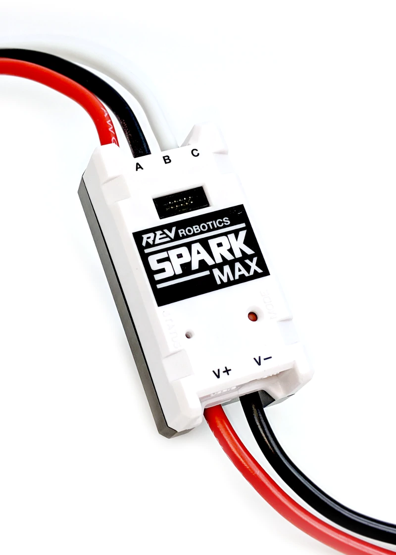
Feature Summary

  • Brushed and sensored-brushless motor control

  • PWM, CAN, and USB control interfaces

    • PWM/CAN - Locking and keyed 4-pin JST-PH

    • USB - USB type C

  • USB configuration and control

    • Rapid configuration with a PC

  • Smart control modes

    • Closed-loop velocity control

    • Closed-loop position control

    • Follower mode

  • Encoder port

    • Locking and keyed 6-pin JST-PH

    • 3-phase hall-sensor encoder input

    • Motor temperature sensor input

  • Data port

    • Limit switch input

    • Quadrature encoder input with index

    • Multi-function pin

  • Mode button

    • On-board motor type and idle behavior configuration

  • RGB status LED

    • Detailed mode and operation feedback

  • Integrated power and motor wires

    • 12 AWG ultra-flexible silicone wire

  • Passive cooling

Kit Contents

The following items are included with each SPARK MAX Motor Controller

  • 1 - SPARK MAX Motor Controller

  • 1 - USB-A male to USB-C cable

  • 1 - 4-pin JST-PH to CAN cable

  • 1 - 4-pin JST-PH to single PWM cable

  • 1 - PWM/CAN cable retention clip

  • 1 - Data port protection cap

Special Thanks

We appreciate the assistance from the community for feedback, contributions, and testing the SPARK MAX, especially .

Team 195 The CyberKnights
Getting Started with the SPARK MAX
Troubleshooting
Status LED Patterns
SPARK MAX Specifications
SPARK MAX Data Port Pinout
Using Encoders with the SPARK MAX
Getting Started with the REV Hardware Client
REVLib API and Installation
MAXSwerve Calibration
SPARK MAX Motor Controller (REV-11-2158)
SPARK MAX Code Examples