
Loading...
Loading...
Loading...
Loading...
Loading...
Loading...
Loading...
Loading...
Loading...
Loading...
Loading...
New for the Igniting Innovation Robotics Challenge, FIRST Global and REV Robotics have partnered to create a new resource to help teams around the world get started quickly! The REV DUO FGC Starter Bot is designed to give teams a starting point for building their robot, while leaving room for iteration, revision, and adaptation to the game’s challenges.
Before our program begins, we need to do some set up first as part of initialization. This section of code will run when "Init" is pressed on the Driver Hub and before "Play" is pressed!
The motors on the drivetrain are mirrored with each other. If we set them to run the same direction then the robot will only spin in a circle! Instead, we will set the left motor to run in reverse allowing us to drive normally.
As for the motors used for the flywheel, because we plan to use velocity we need the encoders enabled to receive proper measurements.
We will be using velocity for the flywheel motors. We can create a variable for our target velocity to make it easy to make adjustments later if we increase or decrease the target.
Velocity is measured in ticks per second.


REV Robotics is proud to partner with FIRST Global, a program designed to bring the ideals and values of FIRST to a global audience through an "Olympics"-style robotics challenge. For more information about the FIRST Global competition, please visit the FIRST Global website.
The FIRST Global robotics kit is powered by the REV Robotics Building System. Below, you will find links to various guides, manuals, instructional videos, and additional products.
Igniting Innovation Playing Field Drawings
Igniting Innovation Playing Field CAD Model
2026 REV DUO FGC Starter Bot
REV Hardware Client Download and User Manual
FIRST Global Youtube
REV Robotics Youtube
Introduction to Structure
Gear Guide
Bearing Guide
Sprockets and Chain
Choosing an Actuator
Tips and Tricks for Building
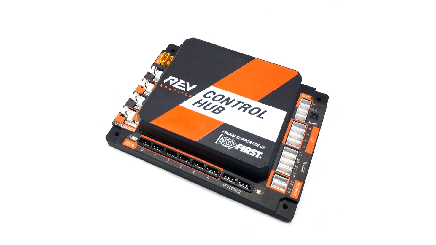
Getting Started with the Control Hub
Getting Started with the Driver Hub
Connecting an Expansion Hub to the Control Hub
Hello Robot - Intro to Blocks Programming
Hello Robot - Intro to OnBot Java Programming
#25 Chain Tool User's Manual
Channel Drivetrain Build Guide


Prior to using this guide, you must understand how to connect the Driver Hub to the Control Hub and create a configuration file for the robot. If this is new to you, please read the Introduction to the DUO Control System guide.
Before programming, connect the Driver Hub to the Control Hub and make sure there is an active configuration file for the robot that contains any devices that you would like to be able to use from a program. See the Configuration section of the Introduction to Programming guide for instructions on creating a configuration file.
Open the main menu on the Driver Station application in the Driver Hub and click on Program & Manage.
The screen will refresh, and then it will look similar to this screenshot. You will have a different network name. At this point, it is recommended to program using a Windows laptop with the REV Hardware Client installed.
For more information on how to access the Control Hub with a computer to program, check out “Where to Program - Client vs. Browser”. The REV Hardware Client allows programming over Wi-Fi or a direct USB connection, however is only available for Windows computers. Browser-based programming must be done through a direct Wi-Fi connection to the Control Hub, but offers an alternative for other operating systems.
Connect your computer to the Control Hub using a USB-C to USB-A cable. The USB-C, or oval end, will plug into your Control Hub, and the USB-A, or rectangular end, will plug into your computer. Once your Control Hub is connected and powered on, open the REV Hardware Client.
Once you have navigated to the Program and Manage tab, you can choose between Blocks or OnBot Java.
Note: These images are from using a laptop to program. The screen layout on the Driver Hub is slightly different, but the icons and buttons are the same.
On the Main screen of the Blocks programming, click on the Create New OpMode button.
Example programs are under Sample.
To open a sample program, first select a program and name the OpMode. Then click the OK button.
The programming screen for Blocks will look like this. Ensure that your configuration/hardware map matches the sample program that you have selected. If you need help configuring your robot, read the guide.
After creating your OpMode, click “Save OpMode” even if you need to make changes to your configuration. This will make sure the OpMode has been properly created and allow you to continue navigating to update or access other programs.
For more information on Blocks programming, read the guide.
Note that these photos are from using a laptop to program. The screen layout on the Driver Hub is slightly different. For OnBot Java, a computer is highly recommended in order to edit the code.
On the Main screen of OnBot Java click on the plus sign (+) to make a New File.
Example programs appear in the Example OpMode “File Type” in the right dropdown menu. There are many examples for OnBot Java.
As of Robot Controller App version 10.3, you can now choose to create a blank template for OnBot Java or pick a sample code to use when getting started.
By default, when creating a new file, OnBot Java will show the file type as “Blank OpMode” with the option to select “Iterative” or “Linear” from the dropdown.
To use a sample program, first select “Example OpMode” from the “File Type” dropdown.
With this file type selected, the example programs are now available to view in the adjacent dropdown.
Selecting one of the example programs will automatically fill in the “File Name” and “OpMode type” options. However, these may also be edited, if needed, to fit your team’s needs.
Note: Using a sample program in OnBot Java will disable the option to select “Add generated code for configured hardware”. When creating a “Blank OpMode”, there is a known bug in v10.3 with the “Add generated code for configured hardware” option not generating code as expected. Motor variables and the hardware map must be manually added.
This is the programming screen for OnBot Java. This screenshot is at the main Java Class of the program.
Make sure that your configuration/hardware map matches the sample program that you have selected. If you need help configuring your robot, read the .
For more information on OnBot Java programming, read the guide.


SRS Programmer
Smart Robot Servo Gear Replacement
UltraPlanetary Gearbox Assembly


It is important that each team’s Control Hub has a unique WiFi network name at the event. This document will show your team how to change the name of your team’s Control Hub before traveling, utilizing a standardized system with International Olympic Committee country codes.
The Control Hub name must be set to XYZ-RC, with XYZ replaced by your team’s unique country code, which can be found at the bottom of this page. Make sure your Control Hub is turned on and connected to your Driver Hub before starting the renaming process.
While connected to the Control Hub, go to the main menu and into Settings.
Scroll down and tap on Robot Controller Name.
The current Robot Controller name will pop up on the screen. Type in the new name (your three-letter country code followed by “-RC”) and click OK. In this example, we are replacing FTC-PQDR with the Control Hub name for country code "XYZ".
Click the back arrow at the bottom of the screen. You should find that you have lost the network connection. If you remain connected to the same Control Hub, repeat the procedure and make sure to press the OK button after typing in the new name.
Go to the main menu and into Settings. Click on Pair with Robot Controller.
Click on the Wi-Fi Settings button.
Click on the new network broadcast by the Control Hub.
If this is the first time you have set your Control Hub to have this network name, you will be prompted for a password. If your team has not changed it, the password will be “password.” Click on Done.
“Connected” should be displayed beneath the Control Hub’s network name.
Use the back arrow at the bottom of the screen to go back to the Driver Station App. The main screen should display the new name.
Congratulations! You have changed the Control Hub name.
Directions for changing the Control Hub’s name and network password through the REV Hardware Client or web browser are .
Version 10.2 and newer of the Robot Controller App/Driver Station App include a warning for teams participating in the FIRST Tech Challenge competition if their device names do not match the FIRST Tech Challenge inspection requirements. This is a cosmetic warning that does not prevent teams from running code or operating normally.
Because FIRST Global follows a different naming convention, this warning can be disabled on the Driver Hub following the directions below:
Go to the main menu and into Settings.
Scroll down until you see “Name Mismatch Warning” in the first section
Tap the on/off toggle to set it to “OFF”
Exit back to the main Driver Station screen, then restart the Driver Hub
Afghanistan
AFG
Albania
ALB
Algeria
ALG


American Samoa
ASA
Andorra
AND
Angola
ANG
Antigua and Barbuda
ANT
Argentina
ARG
Armenia
ARM
Aruba
ARU
Australia
AUS
Austria
AUT
Azerbaijan
AZE
Bahamas
BAH
Bahrain
BRN
Bangladesh
BAN
Barbados
BAR
Belarus
BLR
Belgium
BEL
Belize
BIZ
Benin
BEN
Bermuda
BER
Bhutan
BHU
Bolivia
BOL
Bosnia and Herzegovina
BIH
Botswana
BOT
Brazil
BRA
Brunei Darussalam
BRU
Bulgaria
BUL
Burkina Faso
BUR
Burundi
BDI
Cabo Verde
CPV
Cambodia
CAM
Cameroon
CMR
Canada
CAN
Cayman Islands
CAY
Central African Republic
CAF
Chad
CHA
Chile
CHI
People's Republic of China
CHN
Chinese Taipei
TPE
Colombia
COL
Comoros
COM
Congo
CGO
Democratic Republic of the Congo
COD
Cook Islands
COK
Costa Rica
CRC
Côte d'Ivoire
CIV
Croatia
CRO
Cuba
CUB
Cyprus
CYP
Czechia
CZE
Denmark
DEN
Djibouti
DJI
Dominica
DMA
Dominican Republic
DOM
Ecuador
ECU
Egypt
EGY
El Salvador
ESA
Equatorial Guinea
GEQ
Eritrea
ERI
Estonia
EST
Eswatini
SWZ
Ethiopia
ETH
Fiji
FIJ
Finland
FIN
France
FRA
Gabon
GAB
Gambia
GAM
Georgia
GEO
Germany
GER
Ghana
GHA
Great Britain
GBR
Greece
GRE
Grenada
GRN
Guam
GUM
Guatemala
GUA
Guinea
GUI
Guinea-Bissau
GBS
Guyana
GUY
Haiti
HAI
Honduras
HON
Hong Kong, China
HKG
Hope
HPE
Hungary
HUN
Iceland
ISL
India
IND
Indonesia
INA
Islamic Republic of Iran
IRI
Iraq
IRQ
Ireland
IRL
Israel
ISR
Italy
ITA
Jamaica
JAM
Japan
JPN
Jordan
JOR
Kazakhstan
KAZ
Kenya
KEN
Kiribati
KIR
Democratic People's Republic of Korea
PRK
Republic of Korea
KOR
Kosovo
KOS
Kuwait
KUW
Kyrgyzstan
KGZ
Lao People's Democratic Republic
LAO
Latvia
LAT
Lebanon
LBN
Lesotho
LES
Liberia
LBR
Libya
LBA
Liechtenstein
LIE
Lithuania
LTU
Luxembourg
LUX
Madagascar
MAD
Malawi
MAW
Malaysia
MAS
Maldives
MDV
Mali
MLI
Malta
MLT
Marshall Islands
MHL
Mauritania
MTN
Mauritius
MRI
Mexico
MEX
Federated States of Micronesia
FSM
Republic of Moldova
MDA
Monaco
MON
Mongolia
MGL
Montenegro
MNE
Morocco
MAR
Mozambique
MOZ
Myanmar
MYA
Namibia
NAM
Naoero
NRO
Nepal
NEP
Netherlands
NED
New Zealand
NZL
Nicaragua
NCA
Niger
NIG
Nigeria
NGR
North Macedonia
MKD
Norway
NOR
Oman
OMA
Pakistan
PAK
Palau
PLW
Palestine
PLE
Panama
PAN
Papua New Guinea
PNG
Paraguay
PAR
Peru
PER
Philippines
PHI
Poland
POL
Portugal
POR
Puerto Rico
PUR
Qatar
QAT
Romania
ROU
Russian Federation
RUS
Rwanda
RWA
Saint Kitts and Nevis
SKN
Saint Lucia
LCA
Saint Vincent and the Grenadines
VIN
Samoa
SAM
San Marino
SMR
São Tomé and Príncipe
STP
Saudi Arabia
KSA
Senegal
SEN
Serbia
SRB
Seychelles
SEY
Sierra Leone
SLE
Singapore
SGP
Slovakia
SVK
Slovenia
SLO
Solomon Islands
SOL
Somalia
SOM
South Africa
RSA
South Sudan
SSD
Spain
ESP
Sri Lanka
SRI
Sudan
SUD
Suriname
SUR
Sweden
SWE
Switzerland
SUI
Syrian Arab Republic
SYR
Tajikistan
TJK
United Republic of Tanzania
TAN
Thailand
THA
Timor-Leste
TLS
Togo
TOG
Tonga
TGA
Trinidad and Tobago
TTO
Tunisia
TUN
Türkiye
TUR
Turkmenistan
TKM
Tuvalu
TUV
Uganda
UGA
Ukraine
UKR
United Arab Emirates
UAE
United States of America
USA
Uruguay
URU
Uzbekistan
UZB
Vanuatu
VAN
Venezuela
VEN
Vietnam
VIE
British Virgin Islands
IVB
U.S. Virgin Islands
ISV
Yemen
YEM
Zambia
ZAM
Zimbabwe
ZIM

The intake is controlled using the bumpers on the gamepad. The left bumper intakes game pieces into the robot while right bumper reverses to output back onto the field.
The flywheel on the Starter Bot is controlled using two motors. These motors need to move at the same time when activated.
When cross is pressed, the flywheels will both spin up to the set target velocity. Then the Core Hex controlling the feeder will wait until both motors are within 100 ticks of the target velocity before activating and feeding game pieces into the flywheel to launch.
The Core Hex motor controlling the feeder into the flywheel can be manually controlled using the Dpad on the gamepad to assist with agitating game pieces and clearing jams.
If the robot is not receiving input from the Dpad or Cross button, then all three motors will return to 0 power.
To aid with fine tuning the flywheels, we can add telemetry to see the current velocity on the Driver Hub. The velocity can be changed by modifying the targetVelocity variable.


The Control Hub has preset PIDF values for the motors in the FIRST Global Kit of Parts, but they are based on a freely spinning motor. When that motor is a part of a mechanism that adds load, the PIDF values should be re-tuned, or else the motor will not perform optimally in RUN_USING_ENCODER mode or RUN_TO_POSITION mode. This guide will teach you how to set the PIDF values for your specific mechanism in your OpMode.
Read the Encoder Basics for Blocks and/or the Encoder Basics for OnBot Java programming guides before reading this guide. In addition, make sure that your Control Hub and Expansion Hub have been updated with the latest firmware (see Updating the Control System).
You can establish basic PIDF values for your mechanism by plugging a simple measurement into a formula. This will be sufficient for most use cases. The measurement you need is the maximum motor velocity of your mechanism. To get this, run a maximum velocity measurement OpMode with a full battery. In this OpMode, it is important that you set your motor’s mode to RUN_WITHOUT_ENCODER and the power to 1. Example velocity measurement OpModes are listed below.
An OpMode like this will display the maximum telemetry for a motor to telemetry. You will need to create variables named maxVelocity and currentVelocity in the Variables section of the left toolbar. Note that you can find the velocity block under Actuators -> DcMotor -> Extended.
Here is the same OpMode written in Java:
package org.firstinspires.ftc.teamcode;

@TeleOp
public class MaxVelocityTest extends LinearOpMode {
    DcMotorEx motor;
    double currentVelocity;
    double maxVelocity = 0.0;

    @Override
    public void runOpMode() {
        motor = hardwareMap.get(DcMotorEx.class, "motor");
        motor.setMode(DcMotor.RunMode.RUN_WITHOUT_ENCODER);
        waitForStart();

        while (opModeIsActive()) {
motor.setPower(1); currentVelocity = motor.getVelocity();
if (currentVelocity > maxVelocity) {
maxVelocity = currentVelocity;
}
telemetry.addData("Current Velocity", currentVelocity);
telemetry.addData("Maximum Velocity", maxVelocity);
telemetry.update();
}
}
}Once you have your maximum velocity (maxV), you can calculate the velocity PIDF values. Your F value is calculated like this:
So if your max velocity is 2600 ticks per second (reasonable for a mechanism that uses the HD Hex Motor), then your F value should be about 12.6.
Then your P value is calculated from your F value:
Then your I value is calculated from your P value:
Your D value should be zero.
So for a maximum velocity of 2600 ticks per second, your velocity PIDF values are:
Regardless of your maximum velocity, you can set the position PIDF values to:
Position-mode PIDF only requires a single value because it also uses the velocity PIDF values.
PIDF values are only remembered for the duration of the OpMode that they are set in, so you must apply them at the beginning of all OpModes that you want them to apply to.
Blocks: In Blocks, you apply velocity and position PIDF values using these blocks (found under Actuators -> DcMotor -> Extended).
When you run your OpMode, you may see an error that says Fatal error occurred while executing the block labeled “call motor.setVelocityPIDFCoefficients”. This indicates that you have not updated your Control Hub or Expansion Hub firmware.
OnBot Java: In Java, you can do the same thing with the following lines of code (your motor variable must be defined as a DcMotorEx instance).
motor.setVelocityPIDFCoefficients(1.26, 0.126, 0, 12.6);
motor.setPositionPIDFCoefficients(5.0)
When you run your OpMode, you may see an error that says User code threw an uncaught exception: UnsupportedOperationException - setting of pidf coefficients not supported. This indicates that you have not updated your Control Hub or Expansion Hub firmware.
You should test your PIDF values by switching to RUN_USING_ENCODER mode, setting the velocity to around half of the measured maximum velocity of your mechanism, and continuously printing the current velocity to telemetry. If the motor does not quickly get close to the specified velocity, you should ensure that you did the math correctly.
For each motor, you are able to set PIDF values for velocity and position. The velocity PIDF values are used to help the motor target a particular speed in RUN_USING_ENCODER mode. In RUN_TO_POSITION mode, the position P value is used to find a target velocity for the motor, and the velocity PIDF values are used to target that velocity. Therefore, it is important to correctly tune your velocity PIDF values before tuning the position P value.
The simplest customization to make to your PIDF values is to tune the position P value. The higher the value is, the faster the motor will move towards the target. However, if the value is too high, then the motor will overshoot the target and begin to oscillate.
The F value is used to make a guess for what the motor power should be in a perfect system, based on the maximum velocity of your mechanism. Therefore, you should leave it at the value calculated in the section titled . The remaining values (P, I, and D) work as they do in any other PID closed-loop system. There are many ways to tune these, which you can research yourself. Remember that the target value is a velocity, not a position. This YouTube video made by Worcester Polytechnic Institute serves as a starting point:


If your team is new to FIRST Global Challenge, or in need of a review, we strongly recommend checking out our updated Hello Robot Programming Guide before diving in!
To begin, let's take a look at the configuration and actuators used in this year's design.
Before getting started with programming, we needed to create a . Below is an overview of how the robot is configured for the TeleOp code to function as expected:
Right click the file below and select "save link as" if the download button does not appear. To put this configuration file on your robot, drag this file into the "FIRST" folder of your Control Hub's file system.
The 2026 FGC Starter Bot uses arcade drive controlled by the left joystick. The robot's forward and reverse motions, along with turning, are all controlled by the left stick together!
More information on programming gamepads for use with your robot can be found at .
REV Robotics Ultraplanetary HD Hex Motor
Expansion Hub
0
rightDrive
REV Robotics Ultraplanetary HD Hex Motor
Expansion Hub
1
leftDrive
REV Robotics Ultraplanetary HD Hex Motor
Expansion Hub
2
climbMotor
REV Robotics Ultraplanetary HD Hex Motor
Control Hub
0
bottomFlywheel
REV Robotics Ultraplanetary HD Hex Motor
Control Hub
1
topFlywheel
REV Robotics Core Hex Motor
Control Hub
2
coreHex
REV Robotics Ultraplanetary HD Hex Motor
Control Hub
3
intakeMotor
Left Joystick
Arcade Drive (forward/back, turn)
Triangle
Climb Forward
Square
Climb Reverse
Cross
Activate Flywheel and Feeder
Left Bumper
Intake Game Pieces
Right Bumper
Outtake Game Pieces


The FGC Starter Bot is designed for arcade drive. The left joystick controls all movement for the robot's drivetrain, forward/back and turning!
The inputs from the joystick will be stored in the set up X and Y variables. However, unlike the targetVelocity constant variable set up during initialization, these variables will update every time the program loops.
Then these variables are used to calculate how much power to give each motor based on the current movement of the joystick.
The FGC Starter Bot uses a single motor for climbing. On the gamepad, pressing triangle will allow the robot to ascend up the brace while square reverses the motor to aid with adjusting while climbing.


AprilTags are coded images similar to barcodes or QR codes. Using a webcam, robots can determine where they are in relation to the image by looking at the size and shape of the AprilTag.
Teams that want to use AprilTags to navigate the playing field should begin by printing PDF AprilTag images. Then, use the provided sample program to test the webcam and printed images. Finally, build off this program to make it your own!
Possible benefits include:
Allows teams to track robot translation (forward, right, left) and rotation (roll, yaw, pitch)
Knowing the location of the robot relevant to a goal can help teams release scoring elements more consistently
Drive team visibility of certain parts of the field may be limited
The 2026 FIRST Global Challenge — Igniting Innovation Robotics Challenge uses five AprilTags, labeled 100–104, located on the front and sides of each SUPPRESSION UNIT, and on the front face of the EXTINGUISHER.
Depending on where a robot is located on the playing field, multiple AprilTag images may be visible at the same time. Robots may use these AprilTags to assist in navigating around the field.
The following resources are required to use AprilTags:
Printed PDF files with the AprilTag images used on the playing field
Sample program for detecting and using AprilTags with Blocks or OnBot Java programming
Tag library (.jar file) containing information about the AprilTags used on the field
AprilTags for the 2026 FIRST Global Challenge – Igniting Innovation Robotics Challenge can be downloaded using the buttons below
The Igniting Innovation Robotics Challenge AprilTag library files, and Blocks and Java samples are available for download using the buttons below.
A PDF viewer is required to view and print the tags.
US and Canada printers (Letter 8.5 in x 11 in)
International (A4)
Here are examples of the correct print settings in Windows (left) and macOS (right):
After printing, check that the size of the marker (which includes the thin black border surrounding the black blocks) matches the size written at the bottom of the page (the thickness of the lines is included in the measurement). At close range, the distances reported by AprilTags should be accurate to within a few millimeters.
The 2026 FIRST Global REV Robotics Kit of Parts includes a Logitech C270 webcam for teams to use in the Igniting Innovation Robotics Challenge. To use the webcam, plug in the USB cable to one of the available USB ports on the Control Hub. The Logitech C270 is a USB 2.0 device, so it will work on either of the Control Hub's USB Ports.
Once the webcam is plugged in, it must be added to the robot configuration. For detailed information about creating or modifying a robot configuration, refer to the following documentation linked here:
An outline of the process is included below.
Save the .jar file on your computer and ensure it is named IgnitingInnovationAprilTagLibrary-1.0.jar
You can do this step using the REV Hardware Client or a web browser.
Sample programs are available to provide an introduction to AprilTag programming. Teams may use portions of this code in their own programs.
The sample Blocks program (.blk file) detects all five AprilTag images and reports the webcam’s location relative to the image. Location is reported in three ways:
XYZ: Right, forward, and up distance (in centimeters) from the tag
PRY: Pitch, roll, and yaw (in degrees) relative to the tag
RBE: Range (in centimeters), bearing, and elevation (in degrees) relative to the tag
Before you begin, download the Igniting Innovation Robotics Challenge Blocks sample program using the button below:
The Logitech C270 webcam is calibrated at a resolution of 640x480. Although the resolution of the webcam can be set higher, this will disrupt the distance calculations performed by the AprilTag software. It is recommended that teams do not change the resolution in their code.
Selecting the AprilTag Library in Windows (Left) and macOS (Right)
The sample program expects the robot configuration to include a webcam called Webcam, if your configuration does not include a webcam or it has a different name it will not work.
See the "Setting up the Webcam" section of the FGC AprilTag Guide for help creating a configuration.
The sample program is now available to run on the Driver Hub. Select IgnitingInnovationAprilTagBlocksSample from the second drop-down menu, and tap INIT.
Tap the play button to run the program. You can now hold the webcam in front of an AprilTag and read the information provided on the Driver Hub display. The sample program will list which AprilTag is visible and calculate the webcam’s location relative to the image.
The sample OnBot Java program (.java file) detects all five AprilTag images and reports the webcam’s location relative to the image. Location is reported in three ways:
XYZ: Right, forward, and up distance (in centimeters) from the tag
PRY: Pitch, roll, and yaw (in degrees) relative to the tag
RBE: Range (in centimeters), bearing, and elevation (in degrees) relative to the tag
Before you begin, download the Igniting Innovation Robotics Challenge Blocks sample program using the button below:
The sample program expects the robot configuration to include a webcam called Webcam, if your configuration does not include a webcam or it has a different name it will not work.
See the of the FGC AprilTag Guide for help creating a configuration.
This can be done using a web browser or the REV Hardware Client.
The sample program is now available to run on the Driver Hub. Select EcoEquilibriumAprilTag sample from the second drop-down menu, and tap INIT.
Tap the play button to run the program. You can now hold the webcam in front of an AprilTag and read the information provided on the Driver Hub display. The sample program will list which AprilTag is visible and calculate the webcam’s location relative to the image.


If the upload is successful, the sample program will appear in a folder called com.firstinspires.ftc.teamcode. You can select the file and click the build icon to build the sample program. The build was successful if the message Build SUCCESSFUL! appears in the bottom console.


The 2026 REV DUO FGC Starter Bot features a modified REV DUO channel drivetrain designed around the needs of this year’s challenge. At the front, a wide intake collects multiple Wildfire game pieces and feeds them into a hopper that can hold 8 to 12 Wildfire. From there, a feeder system delivers game pieces into a dual-motor launcher for repeated scoring. Near the end of the match, the climbing system is designed to position the robot at the top of the brace. Overall, the design gives teams a functional starting point while leaving plenty of room to test, tune, and improve mechanisms for their own strategy.
A PDF viewer is required to view and print the templates.
US and Canada printers (Letter - 8.5 in x 11 in)
International (A4 - 210mm x 297mm)
Here are examples of the correct print settings in Windows (left) and macOS (right):


