The REV Control Hub is an affordable robotics controller providing a platform for the interfaces required for building robots. The Control Hub works with the Expansion Hub and Driver Hub to create a complete robotics control system for both the classroom and the competition. These devices are most commonly used within the FIRST Tech Challenge (FTC), FIRST Global Challenge (FGC), and in the classroom for educational purposes.
How to use this documentation?
This documentation is intended as the place to answer any questions related to the REV Robotics Control Hub, Driver Hub, and Expansion Hub used in the FIRST Tech Challenge and FIRST Global Challenge.
Have a specific question? Feel free to head straight to it using the navigation bar to the left. Each section is grouped with other topics that are similar.
Having trouble finding what you are looking for? Try the search bar in the upper right or read the section descriptions below to find the best fit.
Getting started building robots can be an intimidating process. The following documentation is here to make getting started a bit easier. There are a number of examples to get started with the Control System and we are committed to adding content to make it more accessible for people to use REV.
If there is a question that is not answered by this space, send our support team an email; support@revrobotics.com. We are happy to help point you in the right direction.
This section covers how the information needed to keep your Control Hub, Expansion Hub, and Driver Hub up to date with the latest software. This section also includes information on using the REV Hardware Client to update, program, and manage these devices as well.
Programming
From just getting started by writing your first OpMode to working with closed loop control, this section covers the information needed to start programming.
Sensors
Sensors are often vital for robots to gather information about the world around them. Use this section to find how to use REV sensors and information on the different sensor types.
Wiring Diagram
Before configuring your Control Hub, devices must be connected to the Control Hub. Below is a sample wiring diagram to show a sample of actuators and sensors usable with the Control Hub.
Wiring Best Practices
Sometimes poorly wired FTC robots can quickly become a tangled mess. Good wire management is crucial for two reasons: it simplifies troubleshooting electrical issues and prevents them from arising in the first place. Here are some helpful tips to keep in mind when wiring your robot effectively.
Use cables with appropriate lengths to avoid excess cluttering the robot. Alternatively, if a cable must be longer than needed, utilize the full length by routing it neatly.
Proper cable management keeps everything organized and accessible. Zip ties and Velcro straps are popular choices for their ease of use and adjustability.
Secure cables away from the areas where the robot might move, such as the drivetrain or arm mechanism.
Label your wires according to their function. This is especially helpful since wires may be difficult to access later, and clear labels will save you time deciphering their purpose.
Double-check your wiring with a smart tug before every practice and match to ensure all connections are secure.
Smart Tug - tugging on a wire to test the connection with a reasonable amount of force.
For more information on the connectors and cables used with the Control Hub see the links below:
The Control Hub (REV-31-1595) and Expansion Hub (REV-31-1153) can each drive up to four DC brushed motors. As mechanisms are added to the robot the number of motor ports may not be sufficient. There are two ways to add more motors to the Control System, either the SPARKmini Motor Controller (REV-31-1230) or adding an Expansion Hub. The Following two rules give a general idea of when to choose one method over another:
If one or two motors are needed, consider using the SPARKmini Motor Controller.
If three to four additional motors are needed, consider adding an Expansion Hub.
There may come a time when you need to determine if connection ports on either the Control or Expansion Hub are shorted. This section will walk you through how to use a common digital multimeter to see if Voltage is still being pushed through the device.
1
Consult your user's manual to make sure the lead connections are plugged into the correct terminals for DC voltage measurement.
2
In our case, we needed to turn the rotary dial to Hz V and press Function to start measuring for Voltage.
3
Make sure to run your code so the motor ports turn on, then touch your leads to the motor port prongs to get a voltage measurement. Since the code is asking the Control Hub to run port 0 at 100% power, if there is no damage, then we should be able to measure output voltage similar to the battery's supplied voltage.
Since a 12V Slim Battery powers the Control System, you should read a range of voltages.
4
Running the same code, the Control Hub runs port 1 at 100% power; if there is no damage, we should be able to measure output voltage similar to the battery's supplied voltage. However, when measuring motor port 1, even though my 12V battery is charged and my code is running, the multimeter isn't reading anything significant. This motor port is likely damaged, and you should contact support or purchase the Control Hub Repair Service.
Identifying a motor port that does not output voltage on a Control Hub means that something within the port's internal motor controller has been damaged. Since this port is no longer functional, it is recommended to use the Control Hub Repair Service or to fix your Hub.
12V Battery Best Practices and Troubleshooting
Best Practices
When first picking up the 12V Slim Battery Charger, you'll notice the switch on the top of the charger may be set to 0.9A. Setting the switch to 1.8A will increase the electrical current when charging your battery.
Plugging a battery that has been used into the charger will illuminate a red LED on the top. When the LED turns green, your battery is finished charging.
Before using your freshly charged battery, be sure to let the 12V Battery cool down as it may be warm from charging up. Once it acclimates to room temperature, it is safe to use.
To remove the battery from the Control Hub, try to avoid pulling on the XT30 sheathing. This can result in the XT30 solder points being exposed.
Do NOT use the 12V Slim Battery if the protective wire sheathing is fraying or severe damage is evident on the battery.
Troubleshooting
If your battery isn't providing power to the Control Hub, check that:
The XT30 connector isn't damaged or loose.
There's no visible damage to the black and red wires.
The fuse isn't tripped; carefully open the black fuse housing on the red wire to see if the fuse bridge is broken. If it is, simply remove the fuse and replace it with a new one.
If you notice that your 12V Slim Battery isn't holding a charge as well as it used to, depending on how old it is, it could be time to replace it.
12V Slim Battery fuses are common 20A fuses that can be purchased in auto stores or online.
Protection Features
The Control (REV-31-1595) and Expansion Hub (REV-31-1153) were designed with a number of protection features built into the device. These include the following:
Reverse battery input protection
Electrostatic discharge (ESD) protection on all connections
Over-current protection
on all power buses
Digital I/O bus
I2C bus
Analog bus
USB
Servo bus per pair (0-1, 2-3, 4-5)
Encoder bus
Over-current monitoring for individual Motor Channels
Keyed and locking connectors
Fail-safe mode at communication loss
Cables and Connectors
The REV Robotics Control Hub (REV-31-1595) connector selection provides a robust high-density solution for the user. All connectors are keyed and locking except for the Servo, 5V auxiliary power, HDMI , and USB ports.
The REV Robotics Control Hub (REV-31-1595)and Expansion Hub (REV-31-1153) integrate a number of feedback sensors. Some of these are user accessible in the latest FTC Android Studio SDK, but others are not yet directly user accessible. These sensors are in some cases also used by the Control Hub and Expansion Hub for internal safety monitoring.
Battery Voltage Monitoring [Accessible]
Integrated 6-axis IMU [Accessible]
Bosch BHI260AP 6-axis absolute orientation sensor
Control Hubs shipped before September 2022 instead feature a BNO055 9-axis IMU
Expansion Hubs shipped before December 2021 include a BNO055 9-axis IMU
Expansion Hubs shipped AFTER December 2021 do not have an IMU
Internally connected to I2C port 0 and configured to address 0x28
Current Monitoring
Battery [Accessible]
I2C Bus [Accessible]
Digital Power Bus [Accessible]
Servo Power Bus [Not Accessible]
Per Motor Channel Current Monitoring [Accessible]
REV Hardware Client
The REV Hardware Client is software designed to make managing REV devices easier for the user. This Client automatically detects connected device(s), downloads the latest software for those device(s), and allows for seamless updating of the device(s).
OpModes, or operational modes, are computer programs that are used to customize or specify the behavior of a robot. Simply put, these are the programs we create!
The Robot Controller on the Control Hub stores and executes the OpModes. The Driver Hub then allows us to initialize, start, or stop these OpModes.
In the SDK, there are two types of OpModes: autonomous (Auto) and teleoperation (TeleOp). Both types of OpModes have initialization, start, and stop features on the Driver Hub.
You can see in the image above that the left arrow (green box) allows for the selection of Auto programs while the right arrow (blue box) shows the TeleOp list.
Below shows an example of how your list of programs may appear:
Autonomous Timer
When an Auto mode is selected, a 30-second timer will appear next to the play button to count down while this program is active. This can be toggled off for testing!
Countdown timer enabled
Countdown timer disabled
While an autonomous program is running, the robot will act independently without input from a gamepad. At the end of the 30-second timer, the robot will automatically stop the code. If needed, a program can also be stopped early same as while running a TeleOp program.
Selecting Auto vs. TeleOp When Making a Program:
After creating a new OpMode in Blocks, you are able to switch between the code being for autonomous or TeleOp on the top toolbar!
Common Errors in Configuration
While there are many errors one may run into in the programming and software world we're going to focus for now on the two major errors that may occur when hardware mapping.
Interface Errors - errors between how an interface should work and how it actually behaves
Runtime Errors - errors that occur when a program is being executed
Interface Errors
Interface errors occur in the SDK when the parameters of the SDK interface are not met. In the hardware mapping process, the most common interface error occurs within the Blocks Programming Tool.
Blocks is designed to simplify the user experience by automatically handling the conversation of the hardwareMap to pre-named blocks. This means while no configuration is active the applicable block options are removed from the dropdown menu on the side. Similarly, if there are only sensors configured in your file then Blocks will not show the blocks used for motors to minimize the sidebar.
For this reason it is important to create a configuration file BEFORE trying to code!
Below you can see a comparison of Blocks when a configuration file is not selected (left) versus when one is active (right):
If you have started a program before configuring or have the wrong configuration selected, activate the correct configuration file on the Driver Hub then reopen your Blocks program after the Robot Controller has restarted.
Runtime Errors
Within the SDK runtime errors occur during initialization or run. One of the most common runtime errors within the Control Hub can be seen below:
There are a few different reasons this error typically occurs:
No configuration file is currently active or created
The incorrect configuration file is active
There is a mismatched name between the configuration file and code (ex: rightmotor vs right_motor)
What results is when the program begins the robot is forced to stop running when the first hardware device is not properly identified. That first hardware device is the one indicated in the error. If there are multiple issues the next will show once the initial is fixed.
Because Blocks handles importing the hardwareMap for you it will additionally show an error when opening a saved OpMode while the wrong configuration file is selected:
Let's start by getting a motor spinning automatically when we hit play on our program!
From the DcMotor menu in Blocks select the block .
Not seeing your motor listed? Be sure the correct configuration has been activated!
The block above will change names depending on the name of the motor in a configuration file. If there are multiple motors in a configuration file the arrow next to test_motor will drop down a menu of all the motors in a configuration.
Add this block to the OpMode within the while loop. In this scenario we want our motor to continually run so long as our OpMode is active:
Select Save OpMode in the upper lefthand corner of the programming interface.
Quick Check!
Try running this OpMode on the test bed and consider the following questions:
How fast is the motor running?
What happens if you change the power from 1 to 5? What about 100?
What happens if you change the power from 1 to 0.3?
This is a good time to experiment with different values to see how our motor reacts. You might notice that setting our power to 5 or even 100 does not make the motor spin any fast than when set to 1. But setting our power to 0.3 significantly slows our motor's speed, right?
Now what happens if you change the power from 1 to -1?
Setting Direction and Power
From our perspective, a power level of 1 probably doesn't sound very strong. However, to our robot the power being set to 1 translates to the motor running at 100%. That would mean setting the power to 0.3 requests the motor to spin at 30% of power.
When we set our power to a negative power, the motor is told to reverse direction while maintaining that power. So if we set our power to -1 then our motor will still run at 100%, but in the opposite direction than when set to 1.
The direction a motor spins may be determined by the power OR may be designated during the initialization process.
Color Sensor Telemetry
We are going to add several telemetry blocks within our program, but let's start by having our robot tell us how much red, green, or blue it sees when looking at an object with our Color Sensor.
For this we will be using the block from the Telemetry menu. We will need three in total, one for each color, which will be entered in the "key".
The "precision" on the block will be changed to 3. Precision sets the number of decimal places!
To "number" we will add the appropriate block from the "Color" menu:
Adding Hue, Saturation, and Value Telemetry
To add telemetry for hue, saturation, and value we will repeat most of the previous process. However, for "number" we will snap in the matching variable block.
Quick Check!
Save your OpMode and give it a try! How do the values change depending on what color object the sensor is looking at?
This feature requires the Color Sensor's LED to be switched on!
Alpha Telemetry
While working on your code, you may have noticed something called "alpha". The alpha value of a surface tells how transparent or opaque it may be.
Using a similar method as before, we can add a telemetry call for the alpha value to see on our Driver Hub.
Detecting Color
We've asked our robot to gather a lot of data with the color sensor. Now let's have it use that information to output an actual color name rather than just a value!
Let's first set up the skeleton of our if/else statement for determining different colors:
Detecting color if/else statement
Once we've added our block we'll click the gear to add the needed "else if" pieces to have enough for all our colors. To each we will add a block from the Logic menu. Next we can add our variable and a block to each side of this logic statement. We want for each if/else our robot to check if the read hue is LESS THAN a set number!
Is the seen hue less than _?
Last we can add our telemetry for our robot to read out information to the Driver Hub based on what it detects:
Added telemetry blocks
Each check will be for a certain color that is within the specified range. "Key" can be changed to "Color" on the telemetry blocks. We can add the colors in first:
If/else statement with colors added
Next we will add our values for the hue ranges. For example, a color that's hue is between 90-149 should appear as green.
Completed if/else statement
The exact hue values may need to be adjusted slightly, but those used above are based on the default conversion of HSV to RGB when using hue to identify color.
You'll notice that "red" is detected for values under 30 and above 350. This is intentional as red is the beginning and end of the RGB spectrum!
Let's snap our If/Else statement into our loop below the "Alpha" telemetry call.
If/Else statement added to the full program.
Save your OpMode and give it a try! You can adjust the values as you need to better reflect the colors available or changes due to lighting in the room.
The time has come to program our robot to respond to our gamepad inputs so we can drive it around! To start we will be focusing on controlling our drivetrain.
Think back to the very start of Part 2 for a moment. We will be programming our robot using the Arcade Style of TeleOp. This means our forward and back movements will be controlled using the y-axis of the joystick while turning will be controlled by the x-axis.
This section will introduce the use of variables as we create our program. This will allow us to set up calculations in our program that will determine what power the motors should receive based on our gamepad's input. How much power each motor receives changes how the robot will move, so it is important to also review this relationship will establishing our code!
Below is a sneak peek at our final program:
Right Stick vs. Left?
Which joystick is used for driving the robot is largely based on driver preference.
For Hello Robot, we will be referencing using the right stick due to the arm control using the Dpad. This can be changed at any time by selecting your preferred option from the dropdown menu on the blocks!
From the math menu grab the and blocks and add them to the respective motor in the block.
Next add the and variables to the formula blocks.
From there the robot will handle the rest as the program runs! Each time our loop cycles, the robot will check the position of our joysticks and quickly adjust the motor power based on its calculations.
Save your OpMode and give it a try!
Full Program
Getting Started with Control Hub
After receiving the Control Hub it is advised to unbox the device, power the Control Hub on, and start the configuration process. Below are the required materials to run through the initial bring up of the Control Hub and links to the different steps of the process.
Next Steps
Being able to connect to the Robot Controller Console, connect a Driver Station to a Control Hub, and the basics of wiring different actuators and sensors is just the start!
This section focuses on the next steps for using the REV Control System, including getting started with programming and best practices for managing the Control Hub and Slim Batteries.
Now that the Control Hub is setup, it is ready to start programming to control a robot.
Hello Robot, available for and , will walk you through the basics of getting started moving motors, using sensors, and programming a basic drivetrain!
In order for the Control Hub to properly communicate with hardware components, you must perform a two part process known as hardware mapping. One of the most important, and commonly forgotten steps, when getting started programming is the creation of the configuration file, which is the first part of the hardware mapping process.
A properly created configuration file, defines each hardware component with a unique name and a port type and number. After attaching hardware components to the Hub, use the Driver Station application to create a configuration, before beginning to program.
Adding an Expansion Hub
If you want to use more than 4 motors or 6 servos, you can add an Expansion Hub to your robot. An Expansion Hub () can be added to a Control Hub() or another Expansion Hub. The Expansion Hub has all of the same ports as the Control Hub but without the wireless capability.
General Troubleshooting
One of the key aspects of troubleshooting is understanding the most common issues that occur in a system. Once those problems, and their indicators, are defined a flow has to be created. For example, a check engine light in a car indicates any number of issues. When a cars check engine light comes on, a mechanic pulls the codes from the car to narrow down the issue to a specific part of the engine. Even if the code leads to a specific part of the engine, like the transmission, it is not always indicative of the exact problem. However, there is a process flow. Each step narrows down the problem to a potential solution. Troubleshooting the REV Control system is no different!
The status LED is the REV Control System equivalent to the check engine light mentioned in the example. Visit the LED Blink Code section to understand what each code is and what it indicates.
Many issues can be solved by systematic troubleshooting without needing to contact REV Support. Take a look at the troubleshooting tips below for help in determining the cause of the issue you are seeing. Should you need to contact us, describing the steps you've taken in detail will help us get you up and running quickly. The section is divided into general best practices, Control Hub (REV-31-1595) troubleshooting and Expansion Hub (REV-31-1153)troubleshooting.
General Best Practices
Before diving into common troubleshooting paths its important to understand the general guidelines, or best practices, for Control System Health.
Charge the Battery - While a charged battery and phone are crucial to a healthy control system in general; it is also helpful to ensure batteries and phones are charged before a match.
Update - The applications, firmware, and operating system have periodic updates to improve the control system. Keeping the control system up to date ensures the best performance!
Isolate the Issue - This is key to effective troubleshooting. Many issues can show the same symptom, so eliminating failure points one at a time is critical to finding the root cause.
DO NOT plug a battery charger into either the Control Hub or Expansion Hub. It will damage the Hub and cause eventual device failure
Maintaining and taking care of the 12V Slim Battery is also important for troubleshooting purposes. All rechargeable batteries have a finite lifespan however following the best practices for the 12V Slim Battery can extend the lifespan of the battery.
ESD Mitigation Techniques
During Match Play or practice on a competition field, some FTC teams may encounter Electrostatic Discharge (ESD) between the foam tiles and the robots. Below are some methods to help mitigate the effects that any ESD may have on your robot.
Ensure that you plug USB devices, such as a Camera, into USB 3.0 Port on your Control Hub. Using the USB 2.0 Port may cause ESD to affect your Control Hub's Wi-Fi Chip
Add a Resistive Grounding Strap, the 470Ω resistor will help minimize high discharge events from robot electronics and the frame
Treat the practice area with an anti-static spray
Other ESD mitigation strategies can be found within the documentation provided by FIRST:
USB Port Care
Regular maintenance of your DUO Control System's USB ports will help prevent issues in the future. Here are a few tips to make sure your hardware stays in good shape.
When plugging in USB cables, don't force the connector too roughly. This can push the USB port into the Control Hub or Driver Hub
Be sure to keep all ports clean and free of debris. Before cleaning with compressed air, be sure to turn off your device
When transporting or storing a Driver Hub, remove all USB cables from the ports
Don't wrap USB cables that are plugged in around the Driver Hub! This will put stress on the USB ports and is the most common cause of USB port damage
Port Pinouts
XT-30 - Power Cable
The XT30 connector is used for connecting a battery and powering a Control/Expansion Hub. Each Control/Expansion Hub has both a Male and Female XT30 connector, as determined from the metal contacts, not the plastic housing. While either connector can provide power to the hub, it is the convention to use the male connector for "power in" to the hub, and to use the female connector for "power out" to a connected secondary device, like an Expansion Hub or XT30 Power Distribution Block, from the single battery source.
Passing power from one device to another in a chain is often called "daisy-chaining."
Most teams will want to use pre-made cables which can be conveniently sourced from the REV Robotics website. However, teams can also make their own cables. These connectors are solder-cup style, do not require any crimping tools, and are available from various online vendors. Because these connectors are an open design, they are manufactured by a variety of sources and quality may vary. AMASS branded connectors are recommended, and are what is used on REV products, but there are many other quality vendors available.
When using the Control Hub (REV-31-1595)or Expansion Hub (REV-31-1153) please note the location of the IMU in the graphic below. The Hub’s orientation may impact the values received from the embedded IMU.
Wi-Fi Radio Location
The Control Hub has an embedded Wi-Fi radio for wireless communication. The antenna is located towards the top of the Control Hub itself. The graphic below shows the location of antenna.
DO NOT put a battery or other Wi-Fi blocking object on top of the Control Hub. This can lead to higher ping times for communication between the Control Hub and the Driver Station.
Driver Hub Wi-Fi Antenna Location
Approximate location of Wi-Fi antenna indicated by the orange line
Control Hub Operating System Changelog
Important security updates for the Control Hub Wi-Fi driver
Reduces the frequency of an issue that could cause the BHI260AP IMU to reset after an ESD event
Updating the Driver Hub
The Driver Hub has two pieces of software that are field upgradable, the Driver Hub Operating System and the Driver Station Application. Both pieces of software are updatable either through the REV Hardware Client or directly on the Driver Hub with the Software Manager.
Driver Hub Software Manager
The Driver Hub has a Software Manager Application pre-installed for updating the Driver Hub. Open the application by pressing on the Software Manager icon. Select the Update All button to update all the software that requires updating.
Make sure the Driver Hub is connected to a Wi-Fi network with access to the internet to download and install the latest software.
The updates can take several minutes to complete. Make sure the Driver Hub is charged or plug in the Driver Hub during the updating process.
REV Hardware Client
Start the REV Hardware Client and connect the Driver Hub to the PC using the USB-A to USB-C cable. Once the Driver Hub is connected, it will show up on the front page of the UI under the Hardware Tab. Select the Driver Hub.
After selecting the Connected Hardware, the Update tab will pop up. Any software that needs updating will have an Out-of-Date notification. Pressing the Update button allows the REV Hardware Client to download the software update and install on the Driver Hub.
Once all the Out-of-Date notifications are cleared, the Driver Hub is fully up to date.
Accessing Log Files
When troubleshooting problems with the REV Control System log files provide indicators of what the status of the Control Hub or Expansion Hub were during an event. Often the first log that is considered is the Robot Controller log, as they are relatively easy to decipher and can be pulled from the Control Hub or Robot Controller. While working through the looking through the XML files, Wi-Fi Log, or Updater Logs in addition to the Robot Controller logs help to paint a full picture.
There are a few ways to access the log files depending on if you are looking to troubleshoot or downloading the log files for REV support to help.
The REV Hardware Client has a Log Viewer that makes it easier to parse overall log files. Through a series of filters, tags, and a search function makes it easy to see what is happening on the Control Hub or Driver Hub during any OpMode run.
To access the Log Viewer, head to the Utilities Tab.
From there you can select and open log files for connected devices or for ones downloaded onto the computer.
Android Studio - Deploying Code Wirelessly
Android Debug Bridge (ADB) utility is the tool used by Android Studio to connect and control Android devices, like the Control Hub. Android Studio, using ADB, allows users to build and install the Robot Controller app onto their Control Hub.
By default ADB supports using a hardwire connection via USB to deploy code to Android Devices. ADB does support a wireless mode where the build and install process is sent over Wi-Fi. The Control Hub is configured to support ADB wireless connections on port 5555. To deploy code over the Wi-Fi connection the user will need to set up Wireless ADB.
Setting Up Wireless ADB using the REV Hardware Client
To set up wireless ADB using the REV Hardware Client you will need a laptop or PC with both Android Studio and the REV Hardware Client installed.
Power on the Control Hub, by plugging the 12V Slim Battery () into the XT30 connector labeled “BATTERY” on the Control Hub.
The Control Hub is ready to connect with a PC when the LED turns from blue to green.
Connect to the Wi-Fi Network created by the Control Hub
Note:
Open the REV Hardware Client and confirm the Control Hub is connected over Wi-Fi
The Control Hub should be listed in the Android Studio devices dropdown
Part 1: Tackling the Basics
Now that we have our Control System all set up and ready to program it's time to get a full robot running, right?
While we will be getting motors moving and sensors sensing during this section, it's important that we first start small. In this section, we'll be working with a simple test bed as we breakdown how to program some of the components that can be connected to the Control Hub.
By tackling these components individually we'll be able to explore more of their capabilities, common uses, and discuss errors that may occur while working with a full robot.
As mentioned, during this section we will be focus first on the concept of testing. Why do you think testing might be important in robotics?
One of the best practices to get into the routine of is testing all your components individually when they are first received. That's where out test bed comes into play. For our test bed we will be sticking to the basics with our components connected directly to our Control Hub rather than something like a Servo Power Module or Expansion Hub. If desired, we could add some mechanical parts, such as a servo horn or wheel, to aid with visualizing our testing, but this is not required.
Creating an OpMode - Blocks
The time has come to create our first OpMode. We want to make sure to choose a clear and unique name each time we make a program. This will help us to find it again later or to communicate with teammates who may also be driving the robot.
In the programming world, there are common naming conventions that have been established to denote variables, classes, functions, etc. OpModes share some similarities to classes, a program-code-template. Thus the naming convention for OpModes tends to follow the naming convention for classes, which has the first letter of every word is capitalized.
While there are standardized naming conventions in programming, at the end of the day you will want to pick something that makes sense to YOU or your team. This might include having your name, team name, a school class period, or similar in your name.
Your OpMode name should not be the same as a created variable name.
To start, in the REV Hardware Client, select the "Program and Manage" menu tab. In the upper left-hand corner of there is a "Create New OpMode"button, click it:
Clicking the "Create New OpMode" button will open a new window to name and, if applicable, select a sample template for a program. For this guide use the default "BasicOpMode" sample and name the OpMode HelloRobot_TeleOp as shown in the image below.
Once the OpMode has been named click 'OK' to proceed forward.
Creating an OpMode will open up the main Blocks programming page. Before moving on to programming, take some time to learn and understand the following key components of Blocks featured in the image below:
Save OpMode - Click this button to save an OpMode to the robot. It is important to save the OpMode any time you stop working on a code, so that progress is not lost. Blocks does not have an autosave feature!
TeleOp/Autonomous - This section of blocks allows users to change between the two types of OpMode: teleop and autonomous.
Categorized Blocks - This section of the screen is where the programming blocks are categorized and accessible. For instance, clicking Logic will open access to programming blocks like if/else statements.
Programming Space - This space is where blocks are added to build programs. Blocks not currently in the use may be dragged off to the side to be clicked back in later or deleted.
Greeting Message - This intro information message may appear when creating a new, empty OpMode. Clicking the ? icon will close this message.
Remember a needs to be completed first before programming! Some blocks or dropdown menus may be hidden from the side menu until a configuration is made active.
Opening Java Viewer:
Blocks includes a nifty tool to view how our code would appear if converted to Java. You can click the button on the far right side to open or close this viewer.
While this feature is designed to aid in the transition between programming platforms, some edits may be required for the Java code to properly compiled if added to an OnBot Java OpMode.
Programming Essentials
During the process of creating an OpMode, the Blocks tool prompted the selection of a sample code. In Blocks, these samples act as templates, providing the blocks and logical structure for different robotics use cases. In the previous section, the sample code BasicOpMode was selected. This sample code, seen in the image below, is the structural shell needed in order to have a working OpMode.
An OpMode can often be considered a set of instructions for a robot to follow in order to understand the world around it. The BasicOpMode provides the initial set of instructions that are needed in order for an OpMode to properly function.
Though this sample is given to users to reduce some of the complexities of programming as they learn; it introduces some of the most important code blocks. Let's take a closer look at some of them!
Comments are blocks of code intended to help you the programmer.
They can be used to explain the function of a section of code. This is especially helpful in collaborative programming environments. If code is handed from one programmer to another, comments communicate the intent of the code to the other programmer.
Programming Servo Basics
Locating the Servo Blocks
Let's start by reviewing how to access servos within Blocks. At the top of the Categorize Blocks section there is a drop down menu for Actuators. When the menu is selected it will drop down two choices: DcMotor or Servo. Selecting Servo will open a side window filled with various servo related blocks.
The block above will change names depending on the name of the servo in a configuration file. If there are multiple servos in a configuration file the arrow next to test_servo will drop down a menu of all the servos in a configuration.
Different block options will appear when using a continuous rotation servo.
Programming Position Movements
Let's start by programming our servo to rotate to the default 1 position!
From the Servo menu, we will primarily be using the block
Add this block to the op mode code within the .
Click on the number block to change from to .
Select Save OpMode in the upper lefthand corner in the programming interface.
Quick Check!
Let's give our program a try. Take a moment to observe what happens.
When running our program for the first time, we should have seen our servo move itself to position 1 and maintain that position. But what happens if we run it again? Does the servo move?
Running our program a second time
Likely, on a second run our servo did not move since it is already at the correct position. Now check what happens if you first manually rotate the servo while the robot is disabled. Once the code is activated again by pressing play we should see it move again!
Note: Servos are designed to maintain their position so long as the robot's program is enabled. Trying to forcibly move the servo while ON may damage it and is not recommended.
If your servo did not move as expected, double check your wiring and port are correct compared to your configuration.
Resetting Back to Zero
The intent of the is to set the position of the servo. If the servo is already in the set position when a code is run, it will not change positions. Lets try adding another block and see what changes.
In this case, we do not want our servo to reset to 0 every time our code repeats. Because of this where do you think we would snap in our block?
Recall when we discussed the section marked by the comment during Programming Essentials. Since we only want our servo to reset ONCE we will request it do so during the initialization process when the code is first activated, but before play is pressed.
Go ahead and click a block into place to match the code below:
Try running this op mode on the test bed and consider the following question:
What is different from the previous run?
In many applications starting the servo in a known state, like at position zero, is beneficial to the operation of a mechanism. Setting the servo to the known state in the initialization ensures it is in the correct position when the OpMode runs.
Take a moment to think about where setting the servo to a known state during initialization may be helpful before moving to the next section!
Programming Servo Telemetry
What is Telemetry?
Telemetry is the process of collecting and transmitting data. In robotics ,telemetry is used to output internal data from the actuators and sensors to the Driver Hub. It is a way for the robot to communicate back to you the programmer what the robot thinks its doing or seeing. This information can then be used to improve your code, make adjustments to a mechanism, or to strategize when driving around the field if competing.
Telemetry blocks in Blocks can be found under the Utilities dropdown menu:
Using Telemetry with Servos
The most useful telemetry from the servo is the position of the servo along its 270° range.
From the telemetry menu, select the block.
Drag the block and place it beneath the if/else if block set. In this scenario, we want our telemetry to be constantly providing output rather than waiting for a designated check.
From the Servo menu pullout the block Drag the Block and attach it to the number parameteron the telemetry blocks.
For the block "key" is a text box we are able to change to help define what the value is being read out to the Driver Hub's screen. Think of it like an answer key or one used on a map to identify symbols.
Only certain blocks can be added to the second parameter based on what is being requested. In this case the parameter number means the data must be a numeric value.
Change the key parameter to "Servo Position"
Give your program a go!
Programming Motors
Modify your OpMode to add the motor related code. For now your completed servo code can be dragged to the side of your work space. You may alternatively choose to create a second program.
What is a Motor?
Just like servos, a motor is a form of actuator. You may picture a dozen different things when you think of a motor, from those used to spin the wheels of a car to the large turbines that allow a plane to fly. For our robots, we will be focusing on DC motors. These are a type of electrical motor that use direct current, or DC, to rotate and produce the mechanical force needed to move an attached mechanism.
For this tutorial, either a Core Hex Motor or HD Hex Motor may be used as long as they have been properly configured on the Driver Hub.
Most standard motors are able to continuously rotate in either direction with an adjustable speed or power. Some motors may also include a built in encoder, which allows them to move to a specified position, similar to a servo, or to collect data like the number of completed rotations!
To access the motor snippets in Blocks we need to look under the Actuators dropdown menu:
You may notice there are several options for blocks under the DcMotor menu. For Hello Robot we will be using those found in the DcMotor menu itself and under Dual.
As the name suggests, the blocks found under Dual are intended for the use of two motors. We will learn more about them in Part 2!
If you do not see the DcMotor menu under Actuators double check your includes a motor and is currently active on the Driver Hub!
Let's get Programming!
In the next few sections, we will be learning to program our motor to first move automatically in different directions then in response to our gamepad inputs. In our final section we will take a look at using telemetry with our motor's built in encoder.
Below is a sneak peek of our final full code:
Programming a Motor with a Gamepad
Driving Motors with the Gamepad
In the previous section you learned how to set the motor to run at a specific power level in a specific direction. However, in most applications, it will be necessary to control the motor with a gamepad, to easily change the direction or power level of a mechanism.
We are able to use a button to set the motor to a specific power or we can program it so it changes based on the direction of one of the gamepad's joysticks!
From the Gamepad Menu in Blocks select the Block.
When using Blocks we are able to snap some blocks together.
Looking at the block you might notice it is the perfect shape to snap into the end of block, over the 1, like a puzzle piece!
This set of blocks will now continually loop and read the value of gamepad #1’s left joystick (the y position) and set the motor power to the Y value of the left joystick.
Quick Check!
Save your OpMode and test it out with your gamepad! Think about the following questions while testing:
What happens when you move the left joystick up a small amount versus a large amount?
What happens if you move the joystick to the left or right along the X-axis?
What happens if you move the joystick at a diagonal or rotate it 360 degrees?
You may notice that when moving along the X-axis nothing happens at the moment. However, once the joystick hits an angle near the Y-axis vertices the motor may start to jitter and spin.
Adjusting Y-axis Direction
When you tested your program, did the motor spin the expected direction while moving the joystick up or down?
In the FTC SDK for most controllers the Y value of a joystick ranges from -1 when a joystick is in its topmost position, to +1 when a joystick is in its bottommost position.
That may be a little confusing to control, but we can add a negative symbol, or negation operator, to the line of code to change the direction of the motor in relation to the gamepad.
From the Math Menu in Blocks select the block in the image below.
Drag the negative symbol block so it snaps in place between the and blocks:
Programming Motor Telemetry
Motors and Telemetry
Recall that telemetry is the process of collecting and transmitting data. There is a lot of useful information our motors could send back to us, but to start let's have it output the power based on the joystick's movement.
Similar to what we did for our servo program, let's add a block from the telemetry menu to the end of our loop:
From the DcMotor menu pullout the block . Drag the block and attach it to the number parameter on the telemetry blocks.
Change the key parameter to "Motor Power"
When the OpMode is run the telemetry block will display the current power based on the joysticks movement. Give it a try!
Full Program
Programming Touch Sensors
Let's start by breaking down how a touch sensor works at its core!
The information collected by a touch sensor comes in two states, also known as binary states. This information is perfect to use with a conditional statement like an if/else statement.
The block collects the binary TRUE/FALSE state from the touch sensor and acts as the condition for the if/else statement.
Let's take a look at our touch sensor block paired with our block:
Take a moment to think what this code is asking the robot to do. We could read this line of code as "If the touch sensor is pressed do ____, else if the touch sensor is not pressed do _____."
Programming Color Sensors
While a touch sensor features a physical switch to gather information, a color sensor makes use of reflected light. By doing so it collects different data to determine how much light it is seeing, the distance to a surface, and of course what color is in front of it.
For our robot we're going to focus on a few key components: hue, saturation, and value. With these we can use something known as the HSV color model to have the robot translate what its seeing into a recognizable color.
HSV is a form of a cylindrical RGB color model used to do things like create color pickers for digital painting programs, to edit photos, and for programming vision code.
Hue, saturation, and value all will play a part in helping our robot tell us what color it detects and allow us to make adjustments for something like a uniquely colored game piece!
Before we tackle colors, let's start with having our robot use the color sensor to tell us how much light is being reflected.
To start, let's grab a block to add to our loop. Our "key" should be set to "Light detected":
Programming Drivetrain Motors
In we learned how to control a single motor by giving it power or input from a joystick. For controlling a drivetrain, we need to be able to control two motors simultaneously to help the robot move. While we could try adding each motor individually, Blocks has a dual motor block available already for just this purpose.
To access the dual block you will need to select the actuators dropdown menu:
Any code from Part 1 should be moved to the side of the workspace or deleted before continuing this section. Alternatively, you may choose to create a new program.
Add the block to op mode while loop.
Use the variable drop down menu on the block to change from arm to rightmotor.
Establishing Variables in Blocks
You may not expect it, but there is a little bit of math that needs to be done to get our robot moving smoothly. But before we dive too deeply into that let's start with the basics of movement we'll need.
To start, create two variables x and y . This can be done within the Variable menu on the lefthand side.
Once created, add the andblocks to the while loop above your existing power block.
Our y variable will be assigned as , which is the y-axis of the right joystick. Remember just like in the y-axis will need to be inversed using the block available from the Math menu.
Next assign x as the , which is the x-axis of the right gamepad joystick. The x-axis of the joystick does not need to be inverted.
Adding a Limit Switch
Something to consider is the physical limitations of your arm mechanism. Just like you have limitations in how far you can move your arms, our robot's arm can only move up or down so far. However, while you have nerves to help you know when you've hit your limit, we need to add something to help prevent the robot from damaging itself or things around it.
This is where the importance of using sensors comes into play. There are a few ways we could limit our mechanism. What do you think they could be?
In this section we're going to look at how to add a limit switch to stop our robot's arm from extending too far. You might recall in our "Programming Touch Sensors" section that we discussed the touch sensor can act like an on/off switch when programmed. Essentially we're going to have the arm of our robot turn its motor off once the limit is met!
For the moment, let's grab the statement made in the previous section to be set off to the side for later use.
Think back to the "Programming Touch Sensors" section, where you learned how to create a basic limit switch program, similar to the one below:
Robot Control Full Program
It's time to bring everything together so to have a fully mobile robot! Returning to our HelloRobot_TeleOp program we can add our arm control to our loop below the drivetrain code.
Full Program
Right Stick vs. Left?
Which joystick is used for driving the robot is largely based on driver preference.
For Hello Robot, we will be referencing using the right stick due to the arm control using the Dpad. This can be changed at any time by selecting your preferred option from the dropdown menu on the blocks!
Downloads
These premade programs do not include control of the Class Bot V2's "claw" servo. To learn about programming a servo visit .
We've tackled the basics. We have a robot able to drive around. What could be next?
Right now our robot is largely dependent on inputs from us as the driver from the gamepad. We've helped it learn to sense a little bit using the touch sensor, but there is still more we can do.
During Part 3 we will be learning how to help our robot navigate the world around it autonomously in different ways. To start we will look at how to use a timer for the robot to keep track of how long it should do something. From there, we will move on to using the built in encoders of the HD Hex and Core Hex Motors.
Encoders are a form of sensor that help collect data for the motor. Some encoders count the number of completed rotations. Others are able to track the exact position of a motor, similar to a servo. The use of encoders brings the need for more math and complex programming, however it will allow your robot to navigate more efficiently.
ElapsedTime - Blocks
Introduction to ElapsedTime
When using our gamepad, we can actively communicate with our robot while our program runs. Our robot waits for our input and acts accordingly until a different command is issued. However, this may not always be the case, such as during the autonomous period of a FTC competition.
Our robot is smart enough to navigate some on its own, however we need to help it along to know what to look for. Eventually, you could work up to your robot being able to navigate using a camera and machine learning or its IMU to sense direction, but for now let's start with one of the built in features of the SDK: ElapsedTime
What do you think of when you think of a timer? A stopwatch? Your phone? Maybe the timer on a microwave or oven? Timers commonly consist of two main categories: count up and count down. You can think about the differences of these two by a comparison like keeping track of how fast a runner did a 100m dash vs. needing to know how much longer our food should cook.
ElapsedTime is a count up timer. Registering the amount of time elapsed from the start of a set event, like the starting of a stopwatch. In this situation, it is the amount of time passed from when the timer is created or reset within the code.
Quick Links:
ElapsedTime Setup
Locating ElapsedTime Blocks:
Before getting started, let's quickly identify where we will find our ElapsedTime blocks. This menu can be found under the Utilities dropdown on our side toolbar.
Setting up the Basics:
For this section, let's start by creating a new OpMode named HelloRobot_ElapsedTime using the BasicOpMode sample.
From the variable menu, add the block to the OpMode below the comment block.
In order to utilize elements of the ElapsedTime, runtime will act as the ElapsedTime variable. Add the block to the block.
Before moving on to the rest of the ElapsedTime structure lets go ahead and add the motor related blocks. Add to the op mode to the while loop.
Remember that on a drivetrain one of our motors will need to be set to run in reverse to prevent the robot from spinning in place! Add the block under the the block set.
ElapsedTime - Multiple Movements
Right now our robot should move forward 3 seconds then stop. What if we wanted our robot to do something else after those 3 seconds? How do we request our program to continue?
To start let's duplicate our existing loop. We can right click on a block to duplicate it. In this case, since our block is a loop, it will duplicate everything within the loop.
We can snap our second loop below the original, however something is still missing. If we want our second loop to start we need our timer to first reset! We can add a block between our two loops.
Notice our second loop also has a call for telemetry data, however the name is the same! Let's edit it to be "Number of Seconds in Phase 2". Keep the names in mind if you duplicate additional loops.
Give your program a test to see what happens. Think about the following while testing:
Moving to a Target Distance
Now that you have created the constant variables needed to calculate the amount of ticks per mm moved, you can use this to set a target distance. For instance, if you would like to have the robot move forward two feet, converting from feet to millimeters and multiplying by the COUNTS_PER_MM will give you the amount of counts (or ticks) needed to reach that distance!
Let's create two more variables called leftTarget and rightTarget. Add the and blocks within the if/then statement that will run once Play is selected.
Right now the main distance factor is COUNTS_PER_MM , however you may want to go a distance that is in the imperial system, such as 2 feet (or 24 inches). The target distance in this case will need to be converted to mm.
Setting Velocity
Velocity is a closed loop control within the that uses the encoder counts to determine the approximate power/speed the motors need to go in order to meet the set velocity.
To set a velocity, its important to understand the maximum velocity in RPM your motor is capable of. For the Class Bot V2 the motors are capable of a maximum RPM of 300. With a drivetrain, you are likely to get better control by setting velocity lower than the maximum. In this case, lets set the velocity to 175 RPM!
Since RPM is the amount of revolutions per minute, a conversion needs to be made from RPM to ticks per second (TPS). To do this, divide the RPM by 60 to get the amount of rotations per second.
Rotations per second can then be multiplied by COUNTS_PER_WHEEL_REV, to get the amount of ticks per second.
Create a new variable called TPS. Add the to the beginning of the if/then statement above the target variables.
Turning the Drivetrain Using RUN_TO_POSITION
Often times, like in the program created during , we use the block to set the drivetrain motors to a set power or power based on a joystick's inputs. The combined power going to both motors help to determine the direction the robot moves or turns.
However, in RUN_TO_POSITION mode the encoder counts are used instead of to dictate directionality of the motor.
Arm Control with Encoders - Blocks
We've covered using encoders for a drivetrain, but what about for a different mechanism, such as an arm? Unlike the drivetrain, the arm does not follow a linear path. This means rather than converting to a linear distance it makes more sense to convert the encoder ticks into an angle measured in degrees!
In the image below two potential positions are showcased for the Class Bot arm. One of the positions (blue) is the position where the arm meets the limit of the touch sensor. Due to the limit, this position will be our default starting position.
From the Class Bot build guide, it is known that the Extrusion supporting the battery sits a 45 degree angle. Since the arm is roughly parallel to these extrusion when it is in the starting position, we can estimate that the default angle of the arm is roughly 45 degrees.
The goal of this tutorial is to determine the amount of encoder ticks it will take to move the arm from its starting position to a position around 90 degrees.
There are a few different ways this can be accomplished. For example, an estimation can be done by moving the arm to the desired position and recording the telemetry feedback from the Driver Station. Alternatively, we can do the math calculations to find the amount of encoder ticks that occur per degree moved.
Part 4: Going Beyond!
Looking to take the next steps with your robot or to learn more about programming? In "Part 4: Going Beyond!" we have additional tutorials and short lessons to explore.
This section may continue to grow in the future so be sure to check back for new updates!
Follow through this tutorial to walk through both options and determine which is the best for your team!
This section is written with the Class Bot V2 in mind, but can be followed with appropriate adjustments, such as mechanism angles, on other robot designs!
Adds support for Auto Channel Selection, where the Control Hub will pick the least busy Wi-Fi channel on the selected Wi-Fi band when it starts up
Migrates all users to Auto Channel Selection on the 5 GHz band by default.
If you find that you are unable to connect to the Control Hub after updating, you should perform a Wi-Fi Factory Reset by holding down the Control Hub's button as it boots, until you see a colorful light sequence. That will reset the Wi-Fi settings and switch to the 2.4 GHz Wi-Fi band.
Allows switching the Wi-Fi band between 2.4 GHz and 5 GHz by holding down the Control Hub's button when the hub has been booted for at least 20 seconds
If version 5.5 or later of the Robot Controller app is installed, the Control Hub's light will blink magenta when the band is switched to 5 GHz, or yellow when the band is switched to 2.4 GHz.
Continuously monitors the Wi-Fi access point status, and will attempt to restart it if it goes down for any reason
Continuously monitors the Robot Controller app, and restarts it if it crashes or hangs (requires version 6.1 or later of the Robot Controller app)
Allows the Robot Controller app to access the current Wi-Fi band and channel
Always backs up the FTC Robot Controller app data before it is uninstalled, in order to preserve Wi-Fi settings
Improves Wi-Fi reliability
Prevents issue that could cause device to boot into recovery mode
When updating from OS 1.1.1 or earlier to OS 1.1.2 or later, the Control Hub will switch to the 5 GHz band, regardless of the previous Wi-Fi band setting. Some devices do not support 5 GHz Wi-Fi, and will not be able to connect to the Control Hub wirelessly while it is using the 5 GHz Wi-Fi band. To switch to the 2.4 GHz band without needing a computer, see the Changing Wi-Fi Band section.
Once in the Robot Controller Console, update your Control Hub's Wi-Fi settings for better performance and network security.
A Driver Station is required to in the REV Control System, to run code remotely. This section walks through the steps of connecting a Driver Station device to a Control Hub.
Showcases what hardware components plug into which ports on the Control Hub.
Once the hardware components are connected to the Control Hub, the basic steps for getting started have been covered. This section covers the important next steps you should take for working with and maintaining your Control System.
In order to manage the Control Hub (REV-31-1595)or programming using the onboard programming languages you must have access to the Robot Controller Console. Follow through the steps in this section to ensure your Control Hub is connecting properly
Required Materials
Depending on the application more motor, sensor, or servo ports maybe needed. If your robot needs more motors adding an Expansion Hub might be necessary. Adding an Expansion Hub adds the same amount of hardware ports as one Control Hub (an additional four motor ports, six servo ports, and all the sensor ports) to the system.
The Control Hub and Expansion Hub are field upgradable devices. When new software is released with new features, bug fixes, and season specific changes users can update the device themselves. Checking for software updates at the start of September and then aboutevery 6-8 weeks is recommended.
To maintain and care for your battery, reference the general best practices on the 12V Slim Battery (REV-31-1302) product page or the information below. This includes how to properly store, charge, and care for your battery on the long term.
All rechargeable batteries have a finite lifespan. Factors that affect lifespan include the number of discharge/charge cycles and the average loading of the battery. The following best practices can help maximize the lifespan of your battery:
Charge rate
Minimum: 1.5A
Maximum: 3.0A
Recommended: 1.8A or 2.0A
Do not overcharge
Disconnect the battery from the charger once it indicates a full charge.
Typical charge time does not exceed 2 hours.
Minimum no-load voltage: 9.0V
Discharging the battery past 9.0V can reduce the lifespan of the battery and can permanently damage the cells.
Periodic dips below 9.0V when under load is expected and OK.
Temperature
Let the battery cool before and after charging.
The battery may feel warm after heavy loading or after charging. This is normal.
For more information on the important of hardware mapping and how to configure your robot please see the page.
Adding a Expansion Hub
For more information on how to add a secondary Expansion Hub please visit our page.
Managing the Control Hub
Information on updating various pieces of software for the Control Hub, Expansion Hub, and Driver Hub can be found in the Updating and Managing section on the left hand list.
Slim Battery Best Practices
Step
Image
Use the XT Extension Cable to connect power between the Control Hub and the Expansion Hub.
Use a 3-pin JST PH cable to connect the RS485 port on the Control Hub to the Expansion Hub.
From the Driver Station choose “Configure Robot”
FIRST Tech Challenge
FIRST Global
FIRST Tech Challenge teams may use one (1) Control Hub and may add one (1) Expansion Hub starting in the 2020-2021 season. Read the official FTC Game Manuals for complete game rules.
FIRST Global teams must use one (1) Control Hub and may add one (1) Expansion Hub to their robot. Read the official FIRST Global manual for complete game rules.
If you are using a configuration file from a 5.5 or earlier version of the Robot Controller Application, you will need to create a new configuration file.
Adding an Expansion Hub to your Robot
When sending logs to REV Support use the REV Hardware Client. The Client will zip all relevant log files, collect some additional information from a form, and then send them to REV for diagnosis. When running through the troubleshooting process at an event, physically connecting to a Control Hub (REV-31-1595) and using the file search of the computer allows access to the files. Alternatively connecting to the Robot Controller Console allows downloading the logs through the manage tab.
Provide 12v Power to the Control Hub.
Plug the USB-C Cable into the top board of the Control Hub and into a PC with the REV Hardware Client installed.
Select the Control Hub from the Connect Hardware.
Click the "Send Diagnostics to REV" Button
1. Provide 12V power to the Control Hub.
2. Plug the USB-C Cable into the top board of the Control Hub and into a PC
3.Navigate to This PC\Control Hub v1.0\Internal shared storage. Robot Controller, Wi-Fi, and Updater logs can be found on this level of the file hierarchy.
4. While in the This PC\Control Hub v1.0\Internal shared storage location, navigate to a folder called "FIRST." The folder should have XML files with a naming convention that mirrors the names of the robot configuration.
1. Download the Android File Transfer App on your MAC
2. Open Android File Transfer.dmg
3. Drag Android File Transfer to Applications
4. Use the USB-C to USB-A cable that came with your Control Hub (or other relevant Android Device)
5. Double-click Android File Transfer
6. Navigate to Control Hub v1.0\Internal shared storage. Robot Controller, Wi-Fi, and Updater logs can be found on this level of the file hierarchy.
7. While in the Control Hub v1.0\Internal shared storage location, navigate to a folder called "FIRST." The folder should have XML files with a naming convention that mirrors the names of the robot configuration.
1. Open the Robot Controller Console
2. Select the Manage page
3. Press the Download Logs button
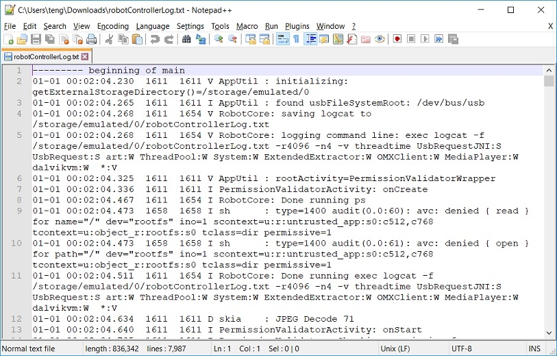
4. Check for the robotControllerLog.txt in the Downloads Directory of the Computer
5. Open the Logs via a text editor, like Notepad++, to view the contents of the log or send the logs to REV Support
For more information on the Log Viewer check out the .
Downloading Log Files
REV Hardware Client
There is a short form to fill out with additional information to help REV Support troubleshoot the issue.
File Search
Using a PC
Mac computers do not support MTP natively; the protocol used to browse files on Android devices. You need to use the Android File Transfer app:
Windows devices will operate without the need for an additional application.
The logs are all text files that can either be open via Notepad++ and looked over or sent to REV Support via an email to be further troubleshot.
Using a Mac
The logs are all text files that can either be open via Notepad++ and looked over or sent to REV Support via an email to be further troubleshot.
Robot Controller Console
in this tutorial we'll be using our test bed to learn about programming basics, however it is highly encourage to maintain a test bed for future testing.
To create our test bed for this tutorial you will need the following. The names we used in our configuration are included:
Component
Configuration Name
1
Control Hub
2
Core Hex Motor
test_motor
The design of a test bed depends on the use case and available resources. For instance, one of the design requirements for the test bed featured here was accessibility. Notice that the placement of the hardware components on the Extrusion allows for the actuators, sensors, and Control Hub to be removed or swapped out with ease.
There are other minor, but important, design considerations to make for a test bed. For example, when adding an actuator to a test bed consider the following questions:
What level of constraint does the actuator need? One of the benefits of creating a test bed for motors, or other actuators, is that the motors can be properly constrained during the testing process. In this case providing basic motion support and constraint is valuable.
How will you be able to tell the behavior of the actuator? The example test bed uses a wheel with a zip tie to help users visualize the behavior of the motor. Tape or other markers can be used, as well.
During Hello Robot you will encounter sections called "Quick Check!" These pauses are intend to be moments to think deeper on a topic or to self-check your understanding as you progress. It's is expected that the completion of Hello Robot may take multiple days, meetings, or classes.
Quick Check!
Why do you think testing might be important in robotics?
Testing before a design is put into use, or as it is being constructed, helps to proactively identify, isolate, and correct potential issues.
Think about it this way:
Imagine spending all day working on building an arm for your robot so it can climb. The design is a little complex, but after an hour or so you have it connected to your robot and everything program.
You go to turn it on for the first time and.... the motor does not move. You can't tell because of where the motor sits if it is damaged or if something is tightened too much preventing it from moving. The rest of the day is spent taking the arm back off to check and repair.
Now think about how things may have gone if we tested the arm before it was attached to the robot. We don't need everything else to move, just a test code to move its motor. Might save us some time right?
Building a Test Bed
Remember when testing a component there may be multiple points of failure such as the port, wire, program, or device itself. Utilizing a test bed helps to narrow down those failure points by making it easier to test and compare in a system's simplest state.
Click to learn more about how a test bed may used in real world applications!
A test bed is a testing environment for hardware and software components, commonly used in the engineering world. Test bed applications includes a broad range of different equipment and measurement testing. In some cases a test bed is a piece of equipment for testing a specific product, in other cases it is a system of components that create a testing environment. Regardless, the end goal of a test bed is to ensure a component is working before it is used for its intended purpose.
Be sure to complete your configuration on the Driver Hub once you have assembled your test bed.
Well a test bed is recommended, in the case of time restrictions, space, or other limitations, individual components may be added or removed during each section of Hello Robot. Make sure moving components, such as motors or servos are ALWAYS secured while running, even at low speeds.
Pre-added blocks like are comments written by the FIRST Tech Team to help with getting started using the provided template.
When using the BasicOpMode template we can see there are three comments already clicked into place:
shows us where we will be establishing variables, resetting encoders, setting motor directions, and anything else that needs to happen when the code is first activated.
is where anything that will be used when hitting the play button on our Driver Hub should be added.
"Put loop blocks here" is similar to our last comment, but is for anything that needs to be repeated the entire time our program is running and will be halted when pressing the stop button.
Take a moment to think where else comment blocks may be useful in a program or to communicate with others.
When the Robot Controller reaches the block it will stop and wait until it receives a Start command from the Driver Hub. Any code after this block will get executed only after the Start button has been pressed.
After the , there is a conditional if block that only gets executed if the OpMode is still active (i.e., a stop command hasn't been received).
You may notice there are two insistences of "opModeIsActive". This allows us to have two options at the start of our program becoming active. The first option has anything that needs to be run only ONCE to be added before our repeat. Then the that follows these blocks is an iterative or looping control structure.
As long as is true those blocks within our loop will remain active when applicable. This is where we will add a majority of our code!
Once the you press the Stop button, the clause is no longer true and the loop will exit.
Key OpMode Blocks
Comments
A variable is a storage location with an associated symbolic name, which contains some known or unknown quantity of information referred to as a value. Variables can be numbers, characters, or even motors and servos.
Where else could we use comment blocks?
Below is an example of comment blocks used in our 2023-24 Starter Bot Programming Demo:
Here you can see a comment block has been added to label where the code for the drivetrain is AND to help instruct a driver on how to control the robot!
Call waitForStart
Call opModeIsActive
If-then (if-else) statements are similar to the concept of cause and effect. If cause (or condition) happens, then perform effect.
In this case it could be read as "If the OpMode is active (or running) then do the following code."
It's always helpful for us to be able to see what the robot thinks its doing on our Driver Hub's screen. To do this, let's request the robot shares some telemetry data while our program is active.
We can access the "Telemetry" blocks under our "Utilities" dropdown on the menu. Look for the block to be added in each section of the if/else statement.
What happens if you run the program right now?
When on the default "Telemetry" block the information provided is not helpful for the robot to communicate with us. Therefore we need to change "key" and "text" to match the desired information.
The "key" should be something related to which sensor, motor, or other device we are receiving information from. Meanwhile "text" will tell us what is happening based on the state of our touch sensor and our if/else statement.
Let's give our code another try to see what happens on the Driver Hub's Screen. Did you see something like the following?
Remember its up to us to decide what our telemetry readout says. With that in mind we could change it so our robot says "Hello World" when the button is pressed:
At the moment, our robot does not have any senses to help navigate the world around it like you might. However, that's the key advantage to adding sensors to our design.
For the touch sensor, one of the most common uses is for it to act as a limit switch. This will help the robot know when it needs to halt the movement of a mechanism, like an arm or lift, that's at its limit similar to how your nerves help to tell your brain to do the same.
We can test this idea by adding on to our existing if/else statement. This time we are going to ask our motor to move until our sensor is pressed using the block:
In the above example theif/else is checking first for if the touch sensor is pressed. The full statement could be read as "If the touch sensor is pressed set the motor's power to 0 else, if it is not pressed, set the power to 0.3".
There may be situations where we want our program to read if the touch is NOT pressed first. Let's take a quick look at how that would function using the block from the "Logic" menu.
Give it a try!
This section applies to the use of the REV Touch Sensor or Limit Switch. Requirements may vary when using other 3rd party touch sensors.
The REV Touch Sensor must be configured to digital port 1, 3, 5, or 7.
It is recommended to create a new OpMode while following this tutorial. Ours is named HelloRobot_TouchSensor!
The touch sensor block is now found under the "Sensors" dropdown as seen below:
Touch Sensor Basics
Remember what sensors and motors are available in your program are determined by your configuration! Double check the correct configuration is active if you do not see a device list.
Adding Telemetry
Take a moment to think about how else telemetry data could be used with your robot before moving on to the next section!
Touch Sensor as a Limit Switch
Reversing it
To the "number" place we will pull a block from the color sensor menu:
Time to test your program to see what your color sensor detects! While testing think about the following questions:
Is the number higher when less or more light is detected?
What happens when the color sensor looks at different color surfaces?
Does the value change when turning the color sensor's LED light on or off?
Does the value change if there is a shadow or if the lighting in the room changes?
Let's start by establishing a few variables in our program.
We'll be going over what a variable is in more detail during Part 2: Robot Control, but for this example we are using them to help our robot translate the data it records more clearly. Our variables will be called "color", "hue", "saturation", "value", and "normalizedColors".
We've discussed how most of these are related to the HSV color model, but what about normalizedColors?
Color Normalization is another technique within vision programming intended to help compensate for differences caused by lighting and shadows when looking at colors. This also affects shades of a color. For example, there are a ton of different shades of blue, such as cyan, navy, and aquamarine, but to our robot these will all be referenced as blue.
Now that we've named our variables, we need to set them to different values.
From our variable menu we need a block. From the dropdown menu, we can change it to "normalizedColors". Next we will snap it in place with a block from the Color Sensor menu below our light detecting telemetry:
Next, let's go ahead and add set blocks for all our variables:
To each we can connect their corresponding block from the Color menu under Utilities:
NormalizedColors is at the bottom of the list.
Next we need to change our variable name from the default of "myColor".
Notice that "color" is matched with NormalizedColors using the matching variable while the rest have the variable set to "color".
From here we can add our telemetry blocks to see what values the color sensor detects!
It is recommended to create a new OpMode while following this tutorial. Ours is named HelloRobot_ColorSensor!
The color and light sensor menus are found under the "Sensors" dropdown as seen below:
Additional blocks to set or call colors are within the "Color" menu under Utilities:
Color Sensor Basics:
But what makes up a color?
Detecting Light vs. Dark
Quick Check!
What happened?
Likely, the numbers and differences you saw while testing are different than those we'd see ourselves. There are many factors that might change the color sensor's readings including the lighting in the room and surface material.
However, one thing that is the same is that 1 should be the least amount of light, such as when your hand is covering the sensor, and 0 is the most amount of light being seen.
Establishing Variables
Defining Variables
Before running your code for the first time, pause and think about the following:
What do you expect your robot to do once the program is activated?
Now save your OpMode using the button in the upper lefthand corner and give your program a go!
DC Motors are capable of spinning in two different directions depending on the current flow provided. When a positive power value is applied the motors will spin in a clockwise direction. The opposite will happen when using a negative power value, meaning the motors will spin in a counter clockwise direction.
But how does that help with our current spinning robot? Let's take a closer look at our physical robot to find out:
Top down view of the Class Bot V2
Notice how the motors on your robot are currently mirrored from each other as part of the drivetrain. Now think about how we learned that when giving the motors a positive value they should turn clockwise. This is still how, however while they may both be rotating clockwise, the direction they know to be as clockwise is opposite.
Motors running the same direction, but facing opposite ways!
Try activating your robot's code again, but this time watching which direction the wheels turn. You may consider supporting the robot's frame so the wheels are suspended to make this easier to see.
There are a couple ways we could adjust our program to help our robot not to be a spinning top. For example, we could make sure the power is set to a negative value whenever one of our motors is called. Or we could simple reverse our motor's direction during initialization.
Add to your program, under the comment block. If you recall, blocks placed in this section will run AFTER the intilizal button is pressed on the Driver Hub, but BEFORE the play button is clicked.
Now with the block added the direction for the rightmotor will always be reversed for this program. Our power values do not need to be changed.
Go ahead and give it a try!
Not seeing DcMotor under the actuators menu? Make sure your configuration has been properly set up and activated before getting started!
Programming Drivetrain Motors
When there are multiple of the same type of variable (such as multiple DcMotors) the variable specific blocks will choose a default variable based on alphabetical order. For this example, OpMode DcMotor blocks will default to the arm variable.
You may have expected your robot to move in a straight line forwards or backwards. Instead, your robot likely spun in a circle.
When motors run at different speeds they spin along their center pivot point. But the motors are both set to a power of 1 here so what else could be the cause?
Always keep the Driver Hub within reach in the case of the event that a robot does not perform as expected. When in doubt, disable your robot to keep you and it safe.
Mirroring Motors
Reversing a Motor:
The and block sets assign values from the gamepad joystick to x and y. Depending on the orientation of the joystick, these valuables will receive some value between -1 and 1.
For a quick reference let's take a look at what number each variable would be assigned at their far ends:
Joystick Direction
0
1
Right now we have x and y assigned values based on our joystick's movement, but what does that mean? Why is that useful?
Maybe you have seen in a math class before something like this:
In this case, a is our variable that has been assigned some value. For this example, we can determine that value is 7. But what does that mean in programming?
Variables used in programming follow this same principle. We can define a variable within our code to hold a set value or a value that changes, such as we are doing here. Then whenever that variable is referenced the robot will read it as that assigned value!
So using our example above if I had:
My robot would know my variable of a is equal to 7 and therefore calculate the answer as 17 for me!
Consider for a moment, why should we use a variable when we could just use the number on its own?
We'll be using variables in greater detail in later sections, but even for our drive code you will be able to see the use of variables helps keep our program clean and easier to follow.
By using setting our variable at the beginning of our code we can inverse it without needing to do so every time we may reference the joystick's y-axis. Within a longer program, having our variables defined at the start would allow us to quickly change a value without having to hunt down or double check that every possible instance in the code has been updated to reflect this change. Instead we are able to change it once and continue testing!
We also learned how the touch sensor operates on a TRUE/FALSE binary. So what is our program above asking the robot to do?
Add the block set back to the code in the else port of the block.
When you tested the above code what happened? You may have encountered a problem where once the touch sensor was pressed the arm could no longer move. This is probably not ideal so why do you think this happened?
One of the advantages of a limit switch, like the touch sensor, is the ability to easily reset to its default state. All it takes is the pressure being released from the button, but right now all our robot knows is that if the switch is pressed it needs to turn off power!
So how do we fix that?
To remedy this, an action to move the arm in the opposite direction of the limit needs to be added to the do statement. Since the touch sensor serves as the lower limit for the arm, it will need to move up (or the motor in the forward direction) to back away from the touch sensor.
To do this we can create an if/else statement similar to our existing gamepad Gamepad if/else ifstatement. In this instance, when the touch sensor andDpadUpare pressed together the arm moves away from the touch sensor. Once the touch sensor no longer reports true, the normal gamepad operations will takeover again!
Now we can snap this into our do statement to complete our code:
This section is designed with the REV Touch Sensor or Magnetic Limit Switch in mind. There may be additional requirements for 3rd party touch sensors.
If you are using a Class Bot your robot should have a Touch Sensor mounted to the front of your robot chassis. You also have a Limit Switch Bumper installed.
Quick Check!
What is our code doing?
Remember that when the touch sensor is pressed it reports as TRUE and while it is NOT pressed it is FALSE.
Right now our robot has been told the motor should be moving at 20% power when the button is not pressed. Once the button is pressed it'll set the power to 0!
Adding Controller Control
While testing, double check the arm mechanism is aligned with the Touch Sensor.
For the Class Bot V2, you may need to adjust the Touch Sensor so that the Limit Switch Bumper is connecting with it more consistently.
Save the op mode and give it a try!
Making Adjustments
Add a block to the block. On the right side of the block add the . One the left side of the add the block.
Add the chosen RPM (175 in this example) to the left side of the block and 60 to the right side.
Now that the target ticks per second has been set, swap the block for a block. Add the to both motors.
Setting our motors to run the specific velocity
With the velocity set, let's give our program a test run after saving!
To convert from feet to millimeters use the following formula:
If you convert 2 feet to millimeters, it comes out the be 609.6 millimeters. For the purpose of this guide, lets go ahead an round this to be 610 millimeters.
Next, multiply 610 millimeters by the COUNTS_PER_MM variable to get the number of ticks needed to move the robot 2 feet. Since the intent is to have the robot move in a straight line, set both the leftTarget and rightTarget, to be equal to 610 * COUNTS_PER_MM
Lastly, we need to change the so that both motors are set to the appropriate target position. To do this add the and blocks to their respective motor.
All of the blocks added to set a target distance
Converting from mm to Feet
Inserting our leftTarget and rightTarget variables
d(mm)=d(ft)×304.8
Converting Feet to Ticks
How long does the robot move?
Could you tell when the robot switched between Phase 1 and 2?
What happens if we change the power in the second loop?
Having multiple loops with different amounts of time can give us a lot of power to help our robot navigate an area. For now let's have our robot complete it's first movement forward for 3 seconds, then reverse back to the start.
This simply requires changing our power in the second loop to -1 !
Quick Check!
Reversing Movement
Since speed an directionality impacts how a robot turns, target position and velocity need to be edited to get the robot to turn. Consider the following code:
Example encoder code with turning
The rightTarget has been changed to be a negative target position. Assuming that the encoder starts at zero due to STOP_AND_RESET_ENCODER this causes the robot to turn to the right.
Notice the velocity is the same for both motors. If you try running this code, you can see that the robot pivots along its center of rotation.
To get a wider turn, try changing the velocity so that the right motor is running at a lower velocity than the left motor. Adjust the velocity and target position as needed to get the turn you need.
Motor Power connections on the Control Hub (REV-31-1595) use the JST VH style connector. This connector is keyed and locking with a small latch, seen below, which must be depressed to release the cable.
Figure 1: How to Use a JST VH Cable
REV Robotics recommends, in most cases, that teams use pre-made cables because crimp quality is better when made using industrial tooling. These cables can be purchased directly from the REV Robotics website or through other online vendors.
Premade JST VH Cables and Accessories
Cable/Accessory
Pins
For teams that want to try crimping their own cables, or to find more information about the connectors, Table 3 lists the appropriate part numbers.
Connector Specifications
10A Continuous Current (16AWG)
3.96mm Pitch
Accepts 22-16AWG Wire
Updating Robot Controller Application
The Robot Controller Application is periodically updated to incorporate fixes, improvements, and new features as they are developed.
If you update your Robot Controller, then you should also update your Driver Station software to the same version number.
There are two ways you can update the Operating System. It is recommended to use the REV Hardware Client as it will automatically notify the user if the Robot Controller Application is out of date, download the latest APK, and install the APK on the device. The second way utilizes the FIRST Robot Controller Console. For using the FIRST Robot Control Console, you will need to download the latest version of the Robot Controller Application from the GitHub repository.
The following procedure works with Control Hubs with the part number REV-31-1595. For support using the REV-31-1152 Control Hub v0 please reach out to REV support (support@revrobotics.com).
Using the REV Hardware Client
Steps
Startup the REV Hardware Client. Once the hub is fully connected it will show up on the front page of the UI under the Hardware Tab. Select the Control Hub.
After selecting the Connected Hardware the Update tab will pop up. Under Robot Controller App select Download.
Once the app has downloaded, select Update.
When the Robot Controller Application update has completed a status message "Robot Controller app update complete." The status of the Robot Controller App will also change to "Up-to-Date."
Welcome to Hello Robot!
The first few pages of Hello Robot are an introduction to the programming tools, configuration, and using a gamepad. Ready to jump right into building and programming? Click here to jump to the or !
The examples and screenshots for this tutorial are completed using a Windows computer, however the Control Hub can be programmed using a Chromebook or a Macbook. Check out " for more information on getting started.
Hello Robot - Choosing Your Path
In almost every programming class for the last 50 years, the first program students learn how to write is "Hello World". This program, and its variations, teach the basics of a new programming language, resulting in code that when run outputs the text "Hello World". Through this basic exercise structure and syntax, or formatting, are taught in a simple code to get students up and running quickly!
While we could display "Hello World!", or in this case "Hello Robot!", on our Driver Hub it may not be enough to help you and your team to get started. Instead, Hello Robot is intended to act as an introduction to the REV Control System. Through this tutorial you will learn the basics of configuration, programming, and utilizing sensors, motors, and servos.
There are two major sections of this tutorial:
Part 1: Building a Test Bed- This section makes use of a basic test bed built of a Control Hub, motor, servo, and touch sensor. Together we will take a look at how to program these devices and discuss the basics of Blocks and OnBot Java!
Part 2: Robot Control- In this section we will be working to get a robot up and moving using a controller, as well as a more detailed look at sensors and encoders.
Before diving in, let's discuss the two program language options available for Hello Robot!
There are two programming languages available to use directly on the Control Hub through either the REV Hardware Client or when using the web browser interface. Additionally, the Control Hub is compatible with Android Studio for those interested in more advanced programming options.
Choosing the appropriate programming tool or language can be one of the most crucial decisions a programmer can make. Thankfully the Software Development Kit (SDK) of the Control Hub has been designed to help new programmers find a starting point and transition to new levels when they're ready.
The following is a breakdown comparison of the available languages and tools:
Basic
Intermediate
Advanced
Take some time to read through the following sections comparing each option to help determine the best option for you or your team:
The Blocks Programming Tool is a drag-and-drop programming tool available directly through the Control Hub. You may recognize it as being similar to other Scratch-based programming languages, such as the blocks coding used in FIRST LEGO League.
Blocks was created to cater to users who have little to no experience programming. Like other visual programming tools, Blocks is a collection of preset code snippets that users can drag-and-drop into the appropriate code line. As you gain more confidence and familiarity with programming, there is a built in option to show the Blocks code in Java's syntax by clicking the "Show Java" button.
OnBot Java is a text-based programming tool based on a modified version of Java that is accessible directly through the Control Hub!
OnBot Java is great for programmers with basic to advanced Java skills who would like to write text-based op modes. OnBot Java shares some of insulative properties of Blocks, but gives you access to the more complicated elements of the SDK libraries. For instance, OnBot requires users to make calls to classes like the hardwareMap, which are hidden within the Blocks code snippets.
An advanced integrated development environment for creating Android apps. This tool is the same tool that professional Android app developers use. Android Studio is only recommended for advanced users who have extensive Java programming experience.
Android Studio allows programmer with an advanced understanding of Java a more powerful development environment to work in. It offers enhanced editing and debugging features not available with OnBot Java or Blocks. It also allows programmers the ability to work with 3rd Party libraries not included within the SDK. However, Android Studio is not a web-based software and will need a dedicated laptop to run on.
To learn about how to properly download and work with Android Studio please visit the
Once you've decided which programming tool you would like to use you can click the link below to go to the appropriate start for Hello Robot!
Exploring Functions
What is a Function?
Functions act similar to a variable in that we are using one thing to represent another. However, where a variable typically is used in place of something short, such as a number, a function can take the place of several lines of code.
This can be incredibly useful if there is a section of code we know will be repeated or to break apart our code into chunks for easy editing.
Creating a new Function in Blocks
If we want to create a new function in our Blocks program, we start by pulling a block from the Functions menu:
Functions menu in Blocks showing the functions from the 2024-25 Starter Bot
Next we will replace "do something" with an appropriate name. Maybe in this case we are adding a new function for climbing:
Example function for climbing
Once our function is named it will appear in the "Functions" menu to be added to the main loop or wherever we need it within our code!
New function block
All that's left is to add whatever code we'd like to be within this function:
If the block is deleted this will remove the function from the "Functions" menu.
Let's say we are working on an autonomous code where we want our robot to drive roughly in a square. Remember that autonomous means this code will move the robot on its own when play is pressed:
Next, let's say we need the robot to do something between one of the turns, such as move its arm or open a servo's claw. There's a couple of ways we could approach this without functions:
Already our code is getting a little long so let's move our side motion and turn into a function:
Now our loop may look like this:
When we test our code we may notice our robot isn't exactly driving in a square shape. Thankfully with our function in place we only need to change the needed value in one place:
This change to the function will be reflected anywhere DRIVE_AND_TURN used.
Give it a try by changing the right motor's power or the timer to refine your square!
Estimating the Position of the Arm
For this tutorial, our OpMode is named HelloRobot_ArmEncoder!
Estimating the Position of the Arm using Telemetry
Let's start by creating a simple program for moving our robot's arm. The one below will look very similar to the code created during Part 2: Robot Control!
A simple program for moving the arm up and down
Adding Telemetry
Within the loop we'll add a block. Add the to the number portion of the block. Change the key string from the default "key" to "Arm Test."
Finding the Position with Telemetry
Save the OpMode and run it.
Use the gamepad commands to move the arm to the 90 degree position. Once you have the arm properly positioned read the telemetry off the Driver Hub to determine the encoder count relative to the position of the arm.
To add the RUN_TO_POSITION code the if/else statement must first be edited back into an block, as shown in the code below.
When DpadUp is pressed, the arm should move to the the 90 degree position. When DpadDown is pressed the arm should move back to the starting position. To do this, set the first equal to the number of ticks it took your arm to get to 90 degrees, for this example we will use 83 ticks.
Since we want DpadDownto return the arm to the starting position, keeping the block set to 0 will allow us to accomplish this. Set both blocks equal to 0.5.
Lastly, we can remove the final "else" of our statement for now since we are now using RUN_TO_POSITION mode.
Despite our power being a positive value for both directions, the arm will move up or down based on the set position!
If you try running this code you may notice that the arm oscillates around the 90 degree position. When this behavior is present you should also notice the telemetry output for the encoder counts fluctuating.
Recall RUN_TO_POSITION is a Closed Loop Control, which means that if the arm does not perfectly reach the target position, the motor will continue to fluctuate until it does. When motors continue to oscillate and never quite reach the target position this may be a sign that the factors determining tolerances and other aspects of the closed loop are not tuned to this particular motor or mechanism.
There are ways to tune the motor, or ways to have the , but for now we want to focus on working with the arm and expanding on how limits and positions work with regards to the mechanism.
Connect to the Robot Controller Console
In order to manage the Control Hub ()or programming using the onboard programming languages, a computer or other Wi-Fi enabled device will need to connect to the Control Hub's Robot Controller Console. The Robot Control Console is a local network created by the Control Hub to program and manage the device.
By default, the Control Hub has a name that begins with "FTC-" or "FIRST-" followed by four characters that are assigned randomly. The default password for the network is "password". If either of these is forgotten, there are a
There are two ways to access the Robot Controller Console. The first will cover how to access the Robot Controller Console with the REV Hardware Client. It is recommended to use the as it will allow the user to access the Robot Controller Console over a wired connection.
The second will run through accessing the .
Updating Wi-Fi Settings
One of the first recommendations made to users of the REV Control System is to update Wi-Fi settings, specifically the name and the password.
All Control Hub's come with a default network name and password. It is useful to change the name and password especially in environments where there are multiple Control Hubs running like at an event or in a classroom. Changing from the default adds an element of network security to the Hub by reducing the potential for access from outside sources.
The Control Hub () can utilize either the 2.4 GHz or 5 GHz Wi-Fi band. REV Robotics advises that during competition teams utilize a 5 GHz channel for robot communication. Consult the table below for Driver Station devices that can operate on the 5 GHz band.
As of the 2024-2025 FTC season, Android phones must be running Android 7 (Nougat) or newer to be compatible with the Driver Station App. Please check the .
Driver Hub Battery Troubleshooting
To install the battery, place it with the REV Logo facing out and the -/+ located near the contacts for the device. Add on the rear door and screw in using the included M3 hardware.
We are aware of some Driver Hubs that were shipped from the factory without having their batteries properly calibrated. If you are experiencing power issues such as trouble charging or being unable to power on the device, try the following:
Plug Driver Hub into a charger without battery (Please use the charger that came with the Driver Hub to ensure a proper calibration)
Expansion Hub Troubleshooting
The following sections, "," provides common indicators of issues seen in the Expansion Hub. Think about what the potential indicators your Hub is currently exhibiting and consider the following questions:
Did you perform a firmware update before the Hub began to have issues?
What is the behavior of the Status LED on the Expansion Hub?
Programming Servos
A servo is a form of actuator or a device designed for moving. With a typical servo, you can specify a target position. The servo will turn its motor shaft to move to the target position, and then maintain that position, even if moderate forces are applied to try and disturb its position.
For Hello Robot we will be using the , which is able to switch between a continuous and angular mode.
Continuous mode allows for the servo to rotate a full 360°, either direction, indefinitely similar to a standard motor.
ElapsedTime Logic
For now our goal will be to have the motors move forward for 3 seconds. To accomplish this we need to edit our main While Loop so that it triggers when the OpMode is active AND the ElapsedTime timer is less than or equal to 3 seconds.
Lets start by creating our less than or equal to condition. Grab the from the Logic menu.
Next select the block from the ElapsedTime menu. Snap the block into the left side of the block. Using the dropdown menu, change the generic to the variable we established earlier.
On the other side of our equation, we need to add a block from the Math menu. Change the number block to 3.
Where to Program - Client vs. Browser
When using Blocks or OnBot Java there are two primary ways to access the Robot Controller App on the Control Hub for programming.
The first way is through the (RHC), the same software you use to update the Control and Driver Hub! This application makes it easy to navigate, manage, update, and program with the Control Hub. Additionally, the RHC allows for programming while connected via USB or Wi-Fi. However, the REV Hardware Client is currently only available for Windows.
As an alternate option, the Robot Controller App can be accessed via Wi-Fi allowing programming through a web browser. This is the perfect option for those using Chromebooks or who may have restrictions on installing applications.
and install on a Windows PC.
Step
Using Limits to Control Range of Motion
In the idea of creating a limit switch was introduced using a physical sensor, like a touch sensor. We can make use of our motor's built-in encoder to do something similar. While a physical sensor would be described as a hard limit, using the built-in encoder is called a soft limit.
To set the soft limits we will build off the program created in the last sections (HelloRobot_ArmEncoder)!
To start, we need to create our upper and lower limits. Create two new variables one called minPosition and one called maxPosition to be added to initialization.
For now we want the minPosition set as our starting position and the
Do not charge a battery that hasn't been discharged significantly.
For example, running the robot under minimal load for a few minutes will not significantly discharge the battery.
For example, don't forget to unplug your battery after you are finished running the robot and don't run your robot until it completely stops responding!
If the update process had to uninstall the previous version of the Robot Controller app, the network name and password for the Control Hub will be reset back to their factory values. If this happens, then you will need to reconnect your computer to the Control Hub using the factory default values.
When the update process is complete and you have successfully reconnected your computer to the Control Hub's network, you should see an "installed successfully" message on the Manage web page.
Power on the Control Hub, by plugging the 12V Slim Battery (REV-31-1302) into the XT30 connector labeled “BATTERY” on the Control Hub.
The Control Hub is ready to connect with a PC when the LED turns from blue to green.
Note: With Robot Controller Application versions 5.5 and below the light will blink blue every ~5 seconds. In 6.0 and above the LED is solid green.
Plug the Control Hub into the PC using a USB-A to USB-C Cable (REV-11-1232)
Updating the Robot Controller App
Click on the FtcRobotController-release.apk link in the repository to access the Robot Controller file.
Click on the Download button to download the Robot Controller app as an APK file to your computer.
On the Manage page, click on the Select App button to select the Robot Controller app that you would like to upload to the Control Hub.
An Update button should appear if an APK file was successfully selected.
Click on the Update button to begin the update process.
During the update process, if the Control Hub detects that the digital signature of the APK that is being installed is different from the digital signature of the APK that is already installed, the Hub might prompt you to ask if it is OK to uninstall the current app and replace it with the new one.
This difference in digital signatures can occur, for example, if the previous version of the app was built and installed using Android Studio, but the newer app was downloaded from the GitHub repository.
Press OK to uninstall the old app and continue with the update process.
and install on a Windows PC.
Steps
Power on the Control Hub, by plugging the 12V Slim Battery () into the XT30 connector labeled “BATTERY” on the Control Hub.
The Control Hub is ready to connect with a PC when the LED turns from blue to green.
Startup the REV Hardware Client. Once the hub is fully connected it will show up on the front page of the UI under the Hardware Tab. Select the Control Hub.
After selecting the Connected Hardware the Update tab will pop up. Select the Program and Manage tab. This will take you to the Robot Controller Console build into the REV Hardware Client.
Once in the Robot Controller Console, the homepage of the console will appear. In the upper right corner is the navigation menu which will allow users to access the Blocks, OnBot Java, and Manage pages within the console.
With the Control Hub powered, access the Wi-Fi network selector. For Windows 10 devices, click the Wi-Fi Network icon in the lower right corner of the desktop.
Look for the Wi-Fi that matches the naming protocol of the device.
Once you have found the target network in the list, click on it to select it then press connect.
Provide the network password (in this example “password”) and press “Next” to continue.
Once a wireless connection is established, the status is displayed in the wireless settings for the device.
Open a web browser (Chrome, Firefox, Edge, Internet Explorer) and navigate to "192.168.43.1:8080" through the address bar.
From the Robot Controller Console users can update the Wi-Fi settings, upgrade the operating system and firmware, as well as program the device. It is strongly recommended that you go through all steps above before you begin programming.
Using the REV Hardware Client
Using a Web Browser
This example assumes the user uses Windows 10 as their operating system. If you are not using a Windows 10, the procedure to connect to the network will differ. Refer to your device’s documentation for details on how to connect to a Wi-Fi network.
REV Hardware Client
You are able to connect to a Control Hub over Wi-Fi or directly through USB-C when using the REV Hardware Client! We recommend connecting via USB to reduce the chance of disconnects.
At this point it is useful to update the , , and the .
Web Browser
When using a Chromebook or Macbook with a Control Hub follow the steps below.
To ensure you are able to locate the correct device, it is recommended that you first connect in a location without other active Control Hubs or significant Wi-Fi connections.
Depending on your version of Windows or other theme settings your Wi-Fi Networks list may vary in appearance.
Passwords are case sensitive. Make sure that your spelling and capitalization matches the original spelling and capitalization for the password.
When connected to the Control Hub, the connected device will not have access to the Internet. It only has direct access to the Control Hub.
Videos
Device
Notes
Wi-Fi Band
REV Driver Hub
2.4 GHz & 5 GHz (Dual Band)
Moto G4 /4th Generation
2.4 GHz (Single Band)
Moto G5
2.4 GHz & 5 GHz (Dual Band)
Moto G5 Plus
2.4 GHz & 5 GHz (Dual Band)
Moto E4
USA Versions only, includes SKUs XT1765, XT1765PP, XT1766, and XT1767
2.4 GHz & 5 GHz (Dual Band)
Moto E5
XT1920
2.4 GHz & 5 GHz (Dual Band)
Moto E5 Play
XT1921
2.4 GHz & 5 GHz (Dual Band)
The following section will highlight how to access and make changes within the Wi-Fi settings. This section will use the REV Hardware Client to showcase how to make these changes. Once a user has connected to the Robot Controller Console, either via the Hardware Client or a web browser, the steps for accessing Wi-Fi settings are the same.
While in the Robot Controller Console select the menu button. In the image below the menu button is highlighted by an orange square in the upper right-hand corner.
When the menu opens, select Manage.
The Manage page is where the Wi-Fi Settings live. The following steps will show and discuss each change as it is made. Please keep in mind the following warning while moving through the steps:
You will need to reconnect to the new Wi-Fi network after changing the name and/or password. This is true for any Wi-Fi connection, but if you are accessing the REV Hardware Client via a USB connection the Hub will stay connected. Though, you may need to close and reopen the Hardware Client in order to see the changes.
Under Wi-Fi Settings, there is an option to change the name of the Control Hub.
For FTC teams you will want to change the name from the default to team number - RC. (i.e. 99999-RC)
Under Wi-Fi Settings, there is an option to change the password of the Control Hub. There are not any restrictions on the password. Changing it from the default is advised but it does not have to change to anything complicated.
The Control Hub is capable of utilizing either the 2.4 GHz or 5 GHz Wi-Fi band. This change is also made within the Wi-Fi Settings.
The Robot Controller Console makes it easy to change between the 2.4 GHz an 5GHz bands. It is advised to check the Legal Android and Wi-Fi Band Capabilities table to determine which band to operate in.
Once a Wi-Fi band is chosen there are two options for dealing with Wi-Fi channels. One option is to let the Control Hub auto default on a channel. The other is to set a specific channel. Both options can be accessed via the drop down menu under the Wi-Fi channel section of the Wi-Fi settings.
It is valuable to know how to change the Wi-Fi Band and Channel as technical staff at an event can request to change those settings.
Legacy Information on Wi-Fi Settings
With the release of Robot Controller Application 5.5 there have been some major changes to the process of changing Control Hub name, password, Wi-Fi Channel, and Wi-Fi band. Previously changes to the name and password had to be made separately. Each change would reset the network and require users to reconnect to the network in order to change anything else. With 5.5 all changes can be made at once.
The Control Hub (REV-31-1595) can utilize either the 2.4 GHz or 5 GHz Wi-Fi band. In OS versions 1.1.1 and older the Control hub defaults to a channel on the 2.4 GHz band.
Supported Android Devices and Wi-Fi Band Capabilities
The following steps assume that users have already connected to the Robot Controller Console. Please go to the if this is not the case.
Steps to Updating Wi-Fi Settings
Not all aspects of the Wi-Fi settings need to be changed. If you need to change name and password and do not need to mess with the Wi-Fi band or channel, leave those settings at default, and click Apply Wi-Fi Settings.
Changing Control Hub Name
It is useful to change the Control Hub name to something unique, especially in environments where there are multiple Control Hubs running like at an event or in a classroom.
Changing the Control Hub Password
The default password 'password' is a well know password by Control Hub users, since it is the default for all Control Hubs. Staying with the default password significantly reduces network security. Changing from the default adds the element of network security back to the Hub by reducing the potential for access from outside sources.
Changing the Wi-Fi Band and Channel
The Wi-Fi band and channel can be changed via the Driver Station Application. For more information on how to make these changes from the Driver Station please see section.
Turn on Driver Hub and verify that the Driver Hub reports 100% battery charge. If the Driver Hub does not report 100% charge, you may be using a PD charger and not the one that came with the Driver Hub.
Install battery into Driver Hub while device is still on and charging
Charge for at least 8 hours and do not remove battery or charge cable
Remove Driver Hub from Charger
Hard Reboot
After completing a battery calibration, use these steps to verify that your battery is functioning as expected.
Place the battery in a Driver Hub and verify that the Driver Hub turns on.
Shake the Driver Hub with the screen still on and verify that the battery does not lose physical contact with the Driver Hub's contacts. If power drops, please see instructions for Unexpected Shutdown above.
Take note of the indicated battery charge level, charge the Driver Hub for 10 minutes, and verify that the battery charge level increased.
If you have the time, perform a full charge/discharge cycle with the battery to verify that the battery behaves normally.
Cut foam tape into small pieces, approximately 2 inches or less long. The foam tape recommended is approximately 1/4 inch or less wide and 1/16 inch or less thick
Foam tape will be applied inside the battery case, opposite battery contacts and below the ridge that the battery door sits within.
Stick foam strip in the middle, both side to side and top to bottom, of the vertical surface opposite the battery contact switch
Press foam strip down firmly to make sure it sticks.
Battery
Insert battery by inserting top of battery towards foam, and gently squeezing battery towards foam with thumb until battery can easily drop into battery case.
Continue to push the battery down until it is flush in the case.
Done
The Driver Hub can enter a "safe" mode intended to protect the battery. This safe mode, also referred to as a battery lockout, keeps your battery and Hub safe by preventing the battery from overcharging and/or keeping the Driver Hub on continuously. This most often happens when the Driver Hub’s battery charge is too low or the device has not been charged for a long period of time.
Symptoms of this lockout mode include:
The Driver Hub only turning on while plugged to the USB without the battery installed.
The Driver Hub appearing to not charge the battery after being connected for long periods of time.
The Driver Hub not turning on with the battery installed and the USB connected.
The Driver Hub not turning on, but the red Status LED lighting up while on USB.
To get the Driver Hub out of the Safe Mode, please follow these steps:
With the battery installed, plug the Driver Hub into its original USB-A Wall Charger and the Orange USB-A to USB-C Cable. The Battery Status LED should blink red at this time, indicating that power is being received.
Let the battery charge for 5 minutes then unplug the Driver Hub. Wait just a moment then plug the Hub back in.
Check to see if the Driver Hub is out of lockout by pressing the power button while the Driver Hub is charging.
If the "Battery charging icon" (red or white) appears on the screen proceed to Step 4.
If you do not see the battery charging icon, please repeat Step 2. Typically, it takes 4-5 cycles of short charging to recover a Driver Hub from this lockout state.
Let charge while completely off for 8 hours to complete a
Contact REV Support with details of the troubleshooting information you have collected such as the answers to the questions above and the outcome of your troubleshooting thus far. It will also help to send logs or other diagnostic data to REV Support.
If you encounter any of these issues below, please email support@revrobotics.com
Device freezes on boot, then restarts the boot process in a loop
Device freezes on boot and never gets into the OS, even after a hard reboot
It is generally recommended to separate the battery from the Driver Hub for long term storage, such as over the summer or a similar long break.
In this troubleshooting guide we will use specific language to describe different ways of power cycling the Driver Hub.
Turn Off/Power Off - Long press (1-2 seconds) the power button so that a drop down menu appears, then tap "power off" on the screen
Hard Reboot - Hold power button for at least 10 seconds and do not touch anything on the screen. Once the green LED light turns off and the screen goes dark, release the power button, and the hard reboot is complete.
Most Common Issues
Battery Installation
Battery Calibration
A battery that is properly installed
Battery Verification
Foam Tape Installation
Battery Lockout Recovery
Still Need Assistance?
Need help getting the Log Files to send to REV Support? See for more information.
Is the Driver Station showing an error message 'Cant find the Expansion Hub Portal"?
Did the Robot Controller app open when you plugged in the RC phone and gave power to the Hub?
Are you experiencing issues with communication between a primary and secondary Hub?
The firmware update failed and the Hub is unresponsive
The Hub is not being recognized or communicating with the phones
Try doing the
There are
The steps below utilize information provided in the Adding an Expansion Hub article. Use this article to help you navigate as you run through the troubleshooting flowchart.
If you are attempting to connect two Expansion Hubs together please confirm that the first Expansion Hub is connected to the Robot Controller. From there change the Expansion Hub address. For information on how to change the Expansion Hub address check out the FTC Wiki Using a Second Expansion Hub article.
The most common cause of a loose or wiggly XT30 port is compressed pins within the male XT30 connector on your Hub. Each pin of the male XT30 connector is made of 4 tines that should have a small amount of space between them. In the image below, the pin on the top has the correct amount of space and the bottom one is visibly compressed, however, an XT30 pin can still be too compressed even if there is visible space.
To help repair compressed XT30 pins, we recommend using an X-ACTO Knife or similar very thin blade to slightly separate the tines. Please use extreme caution when doing this repair as expanding the tines too far can cause the XT30 connector to not fit.
After slightly separating the tines, the male and female XT30 connectors should have a more secure connection.
Click the arrow next to Universal Serial Bus Controllers
Find USB Serial Converter under the menu
If this is not present there maybe a larger issue with your hub. Email support@revrobotics.com with details of the steps you have taken so far and any order numbers for the Expansion Hub (if you have them)
Unplug the USB from your RC phone
Power off the main robot switch (turn off 12V power from the Expansion Hub(s))
Wait a few seconds
Turn on the Main Robot Switch (supply 12V power to the Expansion Hub(s))
On your RC phone, press the square button and the swipe to close the FTC RC app
Plug your RC phone into the USB-- the FTC app should automatically open
If the app doesn't automatically open, you do not have a good connection from the Expansion Hub to the Phone. Check your cables first, followed by the micro and mini USB connections.
Consider using some form of strain relief (like the or one of the many 3d printable options available on places like Thingiverse) to keep the USB-mini port from being damaged.
Contact REV Support with details of the troubleshooting information you have collected such as the answers to the questions above and the outcome of your troubleshooting thus far. It will also help to send logs or other diagnostic data to REV Support.
If a path in this guide does not resolve the issue please contact REV Robotics Support at support@revrobotics.com
Common Indicators and their Solution Steps
Expansion Hubs purchased AFTER December 2021 no longer include an internal IMU
Issues Connecting Control Hub to an Expansion Hub
To update a Robot Controller check out the article on .
XT30 Pins are Compressed
Again, please remember that this repair needs to be done carefully, as overextending the tines of the XT30 connector can cause them to become weakened and hold their shape less. Because of the nature of this kind of damage or wear to your Hub, compressed or overextended pins are not covered under warranty.
Firmware Update
USB Serial Converter Check
If you are using a Mac you can use System Information in Lion or later (or System Profiler in Snow Leopard and earlier versions of Mac OS) in Spotlight (press ⌘ and Space ). The program is in /Applications/Utilities and is the tool to see the connected USB devices and other hardware details.
Expansion Hub Power Cycle
If the issues persist after applying the Retention Mount, try running through the procedure.
Still Need Assistance?
Need help getting the Log Files to send to REV Support? See for more information.
Angular mode
sets the servo to move to specified positions within a 270° range of motion.
Let's take a look at how to program our servo while it is on angular mode:
While most common servos have a range of 180° for motion, the Smart Robot Servo has a range of 270° due to its ability to switch between modes. When programming this means our 0 and 1 position might be a little different than what you'd expect.
Looking at the image above we can see that on default when asking our servo to move to its position 0 it will be at -135° . On the opposite end, moving to its position 1 takes our servo to +135° . Therefore if we wanted to return to 0° we would need to program it to move to its position 0.5.
Let's review quick our basic positions:
Programmed Position
Degrees
0
-135°
0.5
0°
1
135°
Based on what we've learned so far, think about the following two questions:
If we wanted our servo to move to -67.5° what position would we program it move to?
If we have programmed our servo to move to position 0.7, what would that equal in degrees?
In the next few sections, we will be learning to program our servo to first move automatically to different requested positions then in response to our gamepad's input.
Below is a sneak peek of our final full code:
What is a Servo?
This section is considering the Smart Robot Servo in its default mode. If your servo has been changed to function in continuous mode or with angular limits it will not behave the same using the code examples below. You can learn more about the Smart Robot Servo or changing the Servo's mode via the SRS Programmer by clicking the hyperlinks.
A servo horn attachment connected to your Smart Robot Servo may effect where 0° appears. We recommend using a SRS programmer to set the servo to zero before adding attachments. This may also be done using the code learned in this section!
Quick Check
Click to reveal the answers
Breaking it down we can see that -67.5° would be half of our movement between 0° and -135° . Therefore, we will set our position to halfway between 0 and 0.5 equaling 0.25.
This second question requires a little more math. Let's think about how far our servo would move for each 0.1 of a position. Our total movement is 270° so if divided by 10 we know 0.1 = 27°. Going from there we can do the math starting from the 0° we know position 0.5 brings us to. Therefore, moving to position 0.7 should be 54°.
For Hello Robot we will only be programming using positions. Understanding their translation to degrees is still important, however, to help think through designing a mechanism. Degrees may also be preferred when using a direct to program the servo.
Let's get Programming!
Right now the is equal to three. Use the arrow next to the equal sign to choose the less than or equal to sign from the dropdown menu.
With our time condition ready, we can set it aside for a moment.
Now let's set up our logic to modify our While Loop.
First, grab an block from the Logic menu. The block we currently have as part of our loop will be moved to the lefthand side.
On the other side, add the block:
This block set will connect where the block originally was. Now the while loop will now activate when both conditions of the AND block are true.
Let's give our OpMode a try and test the following scenarios:
What happens when hitting play quickly after the initialization button is pressed?
What happens when hitting play 2 seconds after the initialization button is pressed?
What happens when hitting play 10 seconds after the initialization button is pressed?
Not being able to pause between initialization and pressing Play is probably not ideal in most situations. It certainly makes tracking how far the robot will travel more challenging, the opposite of what we'd like ElapsedTime to help us do.
To keep this from happening the timer should be reset once the OpMode is active. Grab the call block from the ElapsedTime menu and switch it to our runtime variable.
This will be added to our program BELOW the comment and ABOVE the while loop.
Since this is before our loop our robot will complete it once when Play is pressed. Then will complete the check for our while loop.
Test your program again with this change!
In previous parts, we've looked at adding telemetry as a way for the robot to communicate with us. In this situation, it would be helpful for the robot to be able to tell us how much time it has counted so we can make adjustments to our program!
Recall we can find our telemetry block under the utilities menu:
Our block will snap into our number slot.
For our key let's call it "Number of Seconds in Phase 1" for now. This will be useful for distinguishing where in our program our robot is during the next section.
Save your OpMode and give it a try!
Setting a Time Limit
Modifying Our While Loop
Quick Check!
What happens while testing?
You may notice the robot moves different distances depending on how long the wait is between INITIALIZATION and PLAYING the program. But why is that?
Remember our timer starts counting when created. Currently, our program creates our timer during initialization meaning it's counting up before Play is ever pressed. If we wait too long our robot may not do anything at all when clicking Play!
Resetting the Timer
Now let's explore what happens when we change our time limit to different amounts. You can adjust your time limit by changing the 3 in our block to a different number.
Consider marking different goals on the floor with tape to practice determining how much time the robot needs to reach it.
Adding Telemetry
Image
1) Power on the Control Hub, by plugging the 12V Slim Battery () into the XT30 connector labeled “BATTERY” on the Control Hub.
2) The Control Hub is ready to connect with a PC when the LED turns green. Note: the light blinks blue every ~5 seconds to indicate that the Control Hub is healthy.
3) Plug the Control Hub into the PC using a USB-A to USB-C Cable ()
Startup the REV Hardware Client. Once the hub is fully connected it will show up on the front page of the UI under the Hardware Tab. Select the Control Hub.
After selecting the Connected Hardware the Update tab will pop up. Select the Program and Manage tab. This will take you to the Robot Controller Console build into the REV Hardware Client.
Once in the Robot Controller Console, the homepage of the console will appear. You will see the option for "Blocks" and "OnBot Java" along the top tool bar. "Manage" provides access to changing the Control Hub's network settings!
With the Control Hub powered, access the Wi-Fi network selector. For Windows 10 devices, click the Wi-Fi Network icon in the lower right corner of the desktop.
Look for the Wi-Fi that matches the naming protocol of the device.
Once you have found the target network in the list, click on it to select it then press connect.
Provide the network password (in this example “password”) and press “Next” to continue.
Once a wireless connection is established, the status is displayed in the wireless settings for the device.
Open a web browser (Chrome, Firefox, Internet Explorer) and navigate to "192.168.43.1:8080" through the address bar.
The Robot Controller App is the application from the SDK, or Software Development Kit, that communicates with the Driver Station App to control the robot. It also contains the programming environments for Blocks and OnBot Java allowing these programs to be saved directly on the Control Hub.
The Hello Robot tutorial focuses on the use of the REV Hardware Client for programming. If you are using the Web Browser to program you will still be able to follow along, but you may see some slight variation in screenshots.
At this point it is useful to update the , , and the .
Web Browser
When using a Chromebook or Macbook with a Control Hub follow the steps below.
To ensure you are able to locate the correct device, it is recommended that you first connect in a location without other active Control Hubs or significant Wi-Fi connections.
Depending on your version of Windows or other theme settings your Wi-Fi Networks list may vary in appearance.
Passwords are case-sensitive. Make sure that your spelling and capitalization match the original spelling and capitalization for the password.
When connected to the Control Hub, the connected device will not have access to the Internet. It only has direct access to the Control Hub.
maxPosition
set to our 90 degree position. Set
minPosition
equal to
and set maxPosition equal to
. The
block previously used for
can be moved to our maxPosition.
To start, our If/Else Statement will be changed back to a simplified format like we had at the beginning of estimating the position of the arm.
If/Else Statement for arm movement
To set the limit we need to edit our if/else statement to include our limits:
Ifup on the Dpad is pressed and the position of the arm is less than the maxPosition, then the arm will move to the maxPosition.
Ifdown on the Dpad is pressed and the position of the arm is greater than the minPosition then the arm will move towards the minPosition.
Use the "logic" dropdown to fill out the statement's check
One of the benefits of having a soft limit is being able to exceed that limit.
Remember that the encoders zero tick position is determined by the position of the arm when the Control Hub powers on! So if we aren't careful to reset the arm before powering on our robot this will effect the arm's range of motion. For instance, if we have to reset the Control Hub while the arm is in the 90 degree position, the 90 degree position will become equal to 0 encoder ticks.
As a back up, we can create an override for the range of motion. There are a few different ways an override can be created, but in our case we are going to use the "A" button and touch sensor to help reset our range.
Start by editing the to add another condition. Use the block as the condition. Add a block to the do portion of the block and set the power to -0.5.
Adding gamepad "A" override
Now that we have this change in place, when the "A" button is pressed the arm will move toward the starting position.
Next, when the arm reaches and presses the touch sensor we want to STOP_AND_RESET_ENCODER .
We can create an additional statement that focuses on performing this stop and reset when the touch sensor is pressed. Check out Programming Touch Sensors from Part 1: Tackling the Basics for review if needed!
Touch sensor limit switch added as a separate If/Else statement
Note: This will show an Expansion Hub Portal if using an Android Device as a Robot Controller
Now you have two Hubs to choose from. Either the Control Hub or the Expansion Hub.
“Expansion Hub 2” is the connected Expansion Hub that is communicating over RS485.
Configure and program as necessary. Please see the Configuration section of for an overview of configuration.
Note: If using an Android Device as a Robot Controller there will be two Expansion Hubs located here. The Expansion Hub Address may need to change so they do not conflict.
If you are new to programming or the REV Control System we recommend that you follow through the whole guide to learn how to properly utilize the system.
This guide is intended to be used with the Control Hub and Driver Hub.
Programming Tools
Blocks
OnBot Java
Android Studio
Hello Robot is not available for Android Studio, but it is important to be aware of all the options available!
This example was originally created as part of the 2024-25 FTC Starter Bot program, but can be followed on a different robot!
After configuring, create a new OpMode to begin. Ours is named FunctionsDemo.
New function added to our main code
Example of a simple code within our function
Simple program for driving in a square
Full code with claw opening after driving two sides
Function containing the code for driving and turning
Using functions to drive in a square
Code for controlling the robot's turn
Remember that the encoder position is set to 0 each time the Control Hub is turned on! This means that if your arm is in a position other than the starting position when the Control Hub is turned on, that position becomes zero instead of the starting position.
Thus far we've tackled a lot of the basics to get parts of our robot moving in response to our gamepad or sensors. So what comes next?
In Part 2 of Hello Robot we're going to look at working with a full, functional robot. By the end of this section your robot will be able controlled with the gamepad!
Before continuing it is recommended to complete, at minimum, a drivetrain. There are a few different options depending on the kit being used. We recommend looking at the , such as what is used with our , or the Class Bot V2!
For this guide the Class Bot V2 is used. for the Class Bot V2!
Create a Basic Robot
The graphic below highlights the major hardware components of the Class Bot V2. These components are important to understand for the configuration process.
In order to continue forward with the Robot Control programming sections, a new configuration file must be made for the components on the robot. It is your choice what variable names you would like to assign to your robot, but for reference this guide will use the following names for each hardware component.
Before continuing it is important to understand the mechanical behavior of different drivetrains. The two most common drivetrain categories types are Differential and Omnidirectional.
Differential Drivetrains are the standard starting drivetrain. They are able to move in forward/reverse, as well as rotate either direction around a central point. There are different styles of directional drivetrains depending on the type of wheels, number of motors, and wheel positions. These include 4WD, 6WD, West Coast, and C-Channel drivetrains.
By comparison, omnidirectional drivetrains can move in any direction with each wheel typically being controlled separately. This allows for advanced forms of navigation, such as strafing, but requires a more complex program. Omnidirectional drivetrains include the use of omni wheels in Y or X configurations, mecanum wheel drivetrains, swerve drive, and other forms of holonomic drives.
While driving our robot with teleop control, we will be giving the robot inputs from our gamepad connected to our Driver Hub. Its job is to translate those inputs to the robot to perform the specified actions. How your robot drives and what joystick does what can be largely dependent on what you or your team's driver is comfortable using. Let's take a look at two of the more common methods of control: Tank Drive and Arcade Drive.
For tank drive, each side of the differential drivetrain is mapped to its own joystick so both will be used. Changing the position of each joystick allows the drivetrain to steer and change its heading. Sample code exists in the Robot Controller Application to control a differential drivetrain in this way.
For arcade drive, each side of the differential drivetrain is controlled by a single joystick. Changing position of the joystick changes the power applied to each side of the drivetrain allowing for a given command.
Arcade drives typically have left/right movement of the joystick set to spin the robot about its axis with forward/back moving the robot forward and reverse.
Arm Control - Blocks
Now that our robot is able to drive around let's get our arm up and moving!
Introduction to Arm Control
Controlling an arm requires a different thought process than the one you used to control the drivetrain. While the drivetrain uses the rotation motion of the motors to drive along a linear distance, an arm rotates along a central point, or joint.
Unlike our drivetrain, our arm has physical limitations for how far it can rotate. We don't want our robot to damage itself so we'll be making use of our touch sensor to act as a limit switch.
Basics of Programming an Arm
For this section, we will start by creating a new program called HelloRobot_ArmControl. We will be able to add this to our drivetrain OpMode later, but for now keeping it separate will help us to focus just on the arm.
To control our arm we will be using the Dpad on our gamepad. While our joystick provides a range of possible values or float data, our Dpad will only be read as 1 or 0. To us these numbers translate to true, the button has been pressed, or false, the button has not been pressed.
Click to Review Boolean vs. Float Data Types!
Boolean data has two possible values: True and False. These two values can also be represented by On and Off or 1 and 0.
The buttons, bumpers, and triggers on the gamepad provide boolean data to our robot! For example, a button that is not pressed will return a value of False (or 0) and a button that is pressed will return the value True (or 1).
Float data is a number that can include decimal places and positive or negative values.
On the gamepad, the float data returned will be between 1 and -1 for the joystick's position on each axis. Some examples of possible values are 0.44, 0, -0.29, or -1.
Let's start by adding an block to our active loop. Use the settings dropdown to change the block to an block.
Now the skeleton of our if/else if statement is ready. We can add the and blocks next.
With this in place our robot will be checking if the Dpad Up or Dpad Down button are pressed before proceeding with the appropriate action. But what do we want our arm to do?
For now, our easiest path is to have our arm move up with DpadUp and down with DpadDown. You may decide later to change which buttons are being used, but the logic found here should be similar.
Let's add a block to each "do" section of our statement. While testing our movement we will want to reduce the power to a more manageable range. For now, we will set our up to 0.2 and down to -0.2.
Save your OpMode and give it a go! Consider the following as test your program:
What happens if you press up on the Dpad?
What happens if you press down on the Dpad?
What happens when neither button is actively pressed?
Did the robot move as you expected?
The current statement tells the robot when the motor should move and in what direction, but nothing tells the motor to stop, thus the arm is continuing to run without limits. Ideally, we want our arm to move ONLY when a button is pressed.
To fix this we can edit the block to have an extra at the end of the statement.
Then add a block to our new "else" section.
With this change in place, save your program and give it another test!
Motor Power vs. Robot Movement
At the moment, our motors are set to power on to a full forward at the start of our program. For reference, the image below shows the full scale of movement between forward and reverse:
Let's take this information and think back to when we first programmed a motor to move with our gamepad. During that section our motor was able to rotate at different power levels depending on how far and in which direction our joystick moved. However, do you recall the problem we had with this set up?
While using our previous code our motor only spun when the joystick was moved along the y-axis. Moving to the left or right did not ask the motor to power on, but it would begin to stutter some at the diagonals.
This is where adding some math to our code comes into play. Remember on an arcade drive both motors are being controlled by a single joystick. We need our robot to be able to calculate for both motors how much they should power on and in which direction. Thankfully, once we have it all set up our robot will be able to handle the calculations itself as the program runs!
By the end, we should be able to create situations like the following charts where the motors respond to create different forms of motion:
How our robot moves is dependent on how much power each motor is receiving. Before continuing, we can explore with our current program how the robot reacts when changing the values in our block.
What happens when we set the power of the rightmotor to 0.3 and leftmotor to 1?
What happens when we set the power of the leftmotor to 0.5 and rightmotor to 1?
What happens when we set the power of the leftmotor to -0.4 and rightmotor to 0.4?
After testing different combinations, let's look at a quick breakdown of how power between the motors effects movement:
Power Comparison
Robot Movement
Rather than setting a static numerical value for our motors, the and blocks will help our robot to translate the motion of the joysticks into a power level.
For our arcade drive, the goal is for our joystick inputs to calculate to the following motor outputs:
To get the outputs expressed in the table above, the gamepad values must be assigned to each motor in a meaningful way. To do so we are going to set up two equations in our code using the variables we have already established:
Programming Mecanum - Simplified
This example is a simplified form of a mecanum drivetrain code intended to review the basics of mecanum movement and is not recommended for a FTC robot.
Check out for a competition ready example!
Configuration
Before getting started with programming we needed to create a configuration file. Below is an overview of how the robot is configured for the TeleOp code to function as expected:
Port Type
Port Number
Device Type
Name
Motor
0
Gamepad Input
Function
For this program, we'll set the motors to RUN_WITHOUT_ENCODER along with their direction
For a mecanum drivetrain all 4 motors will be given a command to follow when the left joystick is moved along the Y-axis of the joystick. For moving forward and back all wheels must turn the same direction.
For this example, strafing is controlled by the left stick's X-axis allowing the robot to slide left and right. In order to achieve this movement, the motors move in diagonal pairs, so frontLeft and backRight will move the opposit direction of backLeft and frontRight, similar to the X shape the wheels make.
Lastly, we have turning set by itself on the right joystick's X-axis. To turn our left and right pairs of wheels will spin in opposite directions.
Encoder Basics
The HD Hex Motor and Core Hex Motor from REV Robotics include a built-in encoder. You may need to check your motor's documentation if following this tutorial with a different vendor's motor.
What is an Encoder?
Encoders are a form of sensor built into some motors that help provide feedback to our robot. There are different kinds of encoders, but we're going to be focus on what's called a quadrature encoder for this tutorial. These encoders are able to count the number of revolutions of the motor also sometimes called "ticks".
While quadrature encoders aren't able to tell exact positions, they can still be used to help the motor move to a specified point. We'll go over how to do so later in this tutorial, but this works by specifying first an origin point in our code then a point the motor should move away.
Quadrature vs. Absolute Encoders
You may see the term absolute encoder when referring to something like REV's . Absolute encoders have a set origin allowing exact movements of the motor in comparison.
Here's a hint for how to remember the difference:
Quadrature Encoders are like a stopwatch continuously adding up time!
Different motors have different numbers of ticks per rotation of the output shaft based on the gear ratio of the motor. When the Control Hub is turned on, all of its encoder ports are at 0 ticks. As a motor moves forward, its encoder value increases. As a motor moves backwards, its encoder value decreases.
Exploring Motor Modes
Let's take a closer look at the different modes we can set our encoder to with our motor. The mode is often established during the initialization process of our code, meaning the motors are ready to go throughout our program, but it is possible to change this for specific use cases as it executes.
Which mode we need to use largely depends on the intended function of the motor and any attached mechanism. For example, we may not need our encoders active on the drivetrain motors when they're being controlled by a joystick's input. On the other hand, we may have a flywheel design that requires a specific speed our encoders can help us achieve.
When using encoders, it is strongly recommended to first use STOP_AND_RESET_ENCODER during initialization. This will allow you to know what position the motor is starting in, however you will want to plan for a repeatable start up configuration each time!
A motor can be switched to "STOP_AND_RESET_ENCODER" while a code is executing as well. This is often set up using a button on the gamepad to allow the driver to reset the encoder in the event of a motor misbehaving, such as after the robot's been caught on an obstacle.
Use this mode when you don’t want the Control Hub to attempt to use the encoders to maintain a constant speed. You can still access the encoder values, but your actual motor speed will vary more based on external factors such as battery life and friction. In this mode, you provide a power level in the -1 to 1 range, where -1 is full speed backwards, 0 is stopped, and 1 is full speed forwards. Reducing the power reduces both torque and speed.
The RUN_WITHOUT_ENCODER motor mode is very straightforward, you simply set a power throughout the program using the "Power" block or, such as for a drivetrain, to be set by the joysticks.
In this mode, the Control Hub will use the encoder to take an active role in managing the motor’s speed. Rather than directly applying a percentage of the available power, RUN_USING_ENCODER mode targets a specific velocity (speed). This allows the motor to account for friction, battery voltage, and other factors. You can still provide a power level in RUN_USING_ENCODER mode, but this is not recommended, as it will limit your target speed significantly.
Setting a velocity from RUN_WITHOUT_ENCODER mode will automatically switch the motor to RUN_USING_ENCODER mode. You should pick a velocity that the motor will be capable of reaching even with a full load and a low battery.
In this mode, the Control Hub will target a specific position, rather than a specific velocity. You can still choose to set a velocity, but it is only used as the maximum velocity. The motor will continue to hold its position even after it has reached its target.
To use RUN_TO_POSITION mode, you need to do the following things in this order:
Set a target position (measured in ticks)
Switch to RUN_TO_POSITION mode
Set the maximum velocity (if not determined by a gamepad input)
Remember it is recommended to always reset the encoder during initialization, however you will need to make sure your robot has been reset physically to the initialization position. For example, an arm may need to be brought back to the start up configuration like for the beginning of a FTC match.
The motor will continue to hold its position even after it has reached its target, unless you set the velocity or power to zero, or switch to a different motor mode.
Configuring Devices
The configuration file is a readable file created by the user through the Driver Station Application. When creating a configuration file users are required to assign each device to a port, select the type of device it is from options provided by the SDK, and give it a unique name.
It's important to name each device something recognizable and distinguishable!
Once a configuration file is saved or activated the robot will restart. This restart is so the SDK can read the file, determine what devices are present, and add the devices to the hardwareMap class.
Select the menu in the stop right corner of the Driver Station app. Then select Configure Robot.
Driver Hub Specifications
The REV Robotics Driver Hub () is a compact mobile computing device designed for interfacing with the Control Hub (REV-31-1595). The Driver Hub was designed and built as an easy to use, dependable, and durable device for use in classroom and the competition. It features an Android operating system, built-in dual band Wi-Fi (802.11 ac/b/g/n/w), and support for many off-the-shelf gamepads and HID devices connected through built-in USB ports. When the Driver Hub software is updated with new features, the device can receive a "field upgrade," through a fast and simple update through the .
The Driver Hub is an approved device for use in FIRST® Global and FIRST Tech Challenge.
Updating Firmware
There are two boards within the Control Hub: an Expansion Huband an Android controller. The Expansion Hub board built into the Control Hub, facilitates a line of communication between the built in Robot Controller and the motors, servos, and sensors. In order to improve the quality of the Hubs, REV Robotics will release firmware updates for the Expansion Hub. When a firmware release occurs, both Control Hub and Expansion Hub users will need to update their Expansion Hub firmware to the newest version.
There are two ways to update the Expansion Hub Firmware. It is recommended to use the as it will automatically notify the user if the Hub's firmware is out of date, download the latest firmware, and install on the device. The second set of steps utilizes the FIRST Robot Controller Console.
To use the FIRST Robot Controller Console, the Manage interface is needed to upload the firmware file to the Control Hub. You can then use a Driver Station that is connected to the Control Hub to initiate the firmware update. You can download the latest firmware below.
Updating Operating System
The Control Hub’s Operating System is field upgradable. New updates are released to incorporate fixes, improvements, and new features as they are developed.
There are two ways you can update the Operating System. It is recommended to use the , as it will automatically notify the user if the Hub's Operating System is out of date, download the latest OS, and install the OS on the device. The second way utilizes the FIRST Robot Controller Console. For using the FIRST Robot Control Console, you will need to download the latest Operating System.
Setting up a Configuration
Before we can truly dive into programming our robot we need to help our robot's brain, the Control Hub, to know what is connected to it. Through the configuration process we can tell the Control Hub which port sensors, motors, servos, and any other connected devices can be found.
This is one of the most important steps to always complete BEFORE you can start programming!
While every REV Control Hub is the same, the robots being controlled are each unique. Each Control Hub has the same number of input and output ports for motors, sensors and cameras, but, how you may utilize these ports varies from system to system. For instance, a Color Sensor V3 may be plugged in to I2C Bus 1 on one person's Hub, but another might use the same bus to host a 2m Distance Sensor.
While the Control Hub may know there is a device attached to a port, it doesn't instinctively know which information needs to be transferred back for use in an . To help our robot out we need to complete a process called hardware mapping. Generally, this is a two step process that includes creating our configuration file using the Driver Hub and calling the hardware map within our OpMode.
When using Blocks, this second step is handled by the SDK itself. Once you've created your configuration file on the Driver Hub your robot's devices are ready to use and you will see their names in the dropdown menus of related blocks.
Drivetrain Encoders - Blocks
Moving the motors to a specific position, using the encoders, removes any potential inaccuracies or inconsistencies from using Elapsed Time. The focus of this section is to move the robot to a target position using encoders.
Before diving in too far, recall that for certain , like the , one of the motors needs to be reversed as the motors are mirrored. In our example, we are adding the block under the .
As introduced in , using RUN_TO_POSITION mode requires a three step process.
The first step is setting target position. To do so, grab the block and add it to under the comment. For this example, we are setting our position after pressing Initialize, but before we hit Play on the Driver Hub.
Calculating Target Position
Now that we have an estimate for our target position let's see if we can refine it to be more precise using similar methods to what we covered during the .
Recall, that ticks per revolution of the encoder shaft is different than the ticks per revolution of the shaft that is controlling a mechanism, such as what we determined on our .
The amount of ticks per revolution of the encoder shaft is dependent on the motor and encoder. Manufacturers of motors with built-in encoders will have information on the amount of ticks per revolution.
In the there are two different Encoder Counts per Revolution numbers:
At the motor - 4 counts/revolution
Welcome to Hello Robot!
In almost every programming class for the last 50 years, the first program students learn how to write is "Hello World". This program, and its variations, teach the basics of a new programming language, resulting in code that when run outputs the text "Hello World". Through this basic exercise structure and syntax, or formatting, are taught in a simple code to get students up and running quickly!
While we could display "Hello World!", or in this case "Hello Robot!", on our Driver Hub it may not be enough to help you and your team to get started. Instead, Hello Robot is intended to act as an introduction to the REV Control System. Through this tutorial you will learn the basics of configuration, programming, and utilizing sensors, motors, and servos.
There are two major sections of this tutorial:
Part 1: Building a Test Bed- This section makes use of a basic test bed built of a Control Hub, motor, servo, and touch sensor. Together we will take a look at how to program these devices and discuss the basics of Blocks and OnBot Java!
Absolute Encoders are more like a clock telling an exact time!
Using STOP_AND_RESET_ENCODER
Using RUN_WITHOUT_ENCODER
Using RUN_USING_ENCODER
Using RUN_TO_POSITION
If the motor is unable to reach the determined position the motor will continue to run attempting to reach or maintain that position, which can lead to the motor stalling and overheating.
The Class Bot V2 uses a directional drivetrain, which will be the drivetrain of focus for this tutorial!
Teleoperated Control Types
Tank Drive
Arcade Drive
Arcade Drive may also be configured as a Split Arcade Drive where one joystick turns the robot while the other controls forward/back. An example of a Split Arcade Drive robot can be found as part of our 2023-24 Starter Bot.
In the USB Devices in configuration page select the Control Hub Portal.
Note: If you have an Expansion Hub connected via USB it will appear as an Expansion Hub Portal.
Within the Hub Portal select the device you want to configure. In this use case, select the Control Hub.
Note: if you have an Expansion Hub connected to a Control Hub via RS485, the Expansion Hub will also appear as a configurable device in the portal.
This will bring you to the page shown in the image. From here you can configure motors, servos and sensors that you are using. Follow through the rest of the guide to figure out how to configure devices that will be used in the Test Bed section.
Note: The way that Digital and Analog devices are configured versus how I2C devices are configure differ significantly. This is because each physical I2C port is a different bus that can host multiple different sensors. For more information on the different types of sensors check out the sensors section.
This walkthrough provides an example of configuring each device type. This process will vary slightly depending on the part in use and decided name.
Configuring a Motor
Select Motors.
The Motor page will allow you to configure all four motor ports on the Hub. For this example, a REV Robotics Core Hex Motor is being configured to Port 0. Select the port and then the motor from the dropdown.
Name the motorthen select done.
Note: When naming hardware in the configuration file the REV Control System isCase Sensitive.
Select done once all motors are added.
Select Servos.
The Servo page will allow you to configure all six servo ports on the Hub. For this example, a servo is being added to Port 0.
Note: REV Smart Robot Servos can be configured as a Servo or a Continuous Rotation Servo. The type of device a servo is configured as should correspond with the mode the sensor is in. For more information visit .
Name the servoand select done.
Note: When naming hardware in the configuration file the REV Control System isCase Sensitive.
Select Digital Devices.
The Digital Devices page will allow you to configure all eight digital ports on the Hub. For this example, a touch sensor is being configured to Port 1.
Note: Touch Sensors must always be configured on odd number ports.
Note: REV Touch Sensors can be configured as a REV Touch Sensor or a Digital Device. In the FTC SDK the type of device it is configured as changes the classes and methods that can be used.
Name the sensor and select done.
Select I2C Bus 0.
Select Add.
Note: Each I2C Bus can host more than one I2C sensor as long as the I2C addresses do not conflict. Bus 0 will always host the internal IMU. For more information on I2C sensors visit the .
On Port 1, which was created in the previous step, open the drop down menu and select the desired sensor. In this example, a REV Color Sensor V3 is being added.
Note: If you are using Color Sensors V1 or V2 selectREV Color/Range Sensor. For more information on configuring with the REV Color Sensors visit the .
After creating a new configuration file, select the Control Hub Portal in the USB Devices menu.
An Expansion Hub connected via RS485 will appear here as a separate portal.
Once in the Expansion Hub's portal, devices can be configured the same as the Control Hub using the directions above. At the top of the menu, it will show if you are within the Expansion Hub or Control Hub's options.
Select Done once all devices are added.
After creating a new configuration file, select the Control Hub Portal in the USB Devices menu.
Select the Servo Hub you wish to configure. It will show the set ID number.
Select Servos.
Servos will be configured the same as for a Control or Expansion Hub from here.
Select Done once all servos are added.
Hit Done twice until you reach the USB Devices in configuration page. On the USB Devices in configuration page hit Save.
Name the configuration then select Ok.
Press back to activate the saved configuration. Your Robot Controller will restart once you activate a new configuration.
The active configuration appears in the upper right on the configuration screen and on the main Driver Station screen.
Learn more about configuration by checking out our Hello Robot tutorial for Blocks or OnBot Java.
Configuring Common Hardware Devices
Accessing the Configuration Utility
Pressing "Scan" on an existing configuration may result in the already named devices being erased. A new configuration file is needed when adding a camera or Expansion Hub.
Configuring Actuators and Sensors
Curious what sensors or devices are natively compatible with the Robot Controller App on the Control Hub? Check our !
Configuring RS485 Devices
Expansion Hub
Configurations are unique to each Expansion Hub. A new configuration file must be created if the Expansion Hub is changed with a different one.
Servo Hub
Saving the Configuration File
Qty
Interface
Description
Power
1
Button
Turns the device on and off
USB C
1
USB C
Connect directly to the Driver Hub via PC, USB 2.0
Supports fast charging the Driver Hub over USB PD
USB 2.0
3
USB A
Connect USB controllers and other HID devices to the Driver Hub
Ethernet
1
RJ45
10/100 base-T
Supports 12V DC passive POE
The following tables provide the mechanical specifications for the Driver Hub.
Feature type
Description
Processor
RKPX30 Quad-core ARM A35
Memory
1GB LPDDR3
†
Supports expandable storage through the SD Card slot
Parameter
Min
Typ
Max
Units
Body length
-
3.375
Please refer to the following guidelines in the event the Driver Hub charger must be replaced:
Power on the Control Hub, by plugging the 12V Slim Battery () into the XT30 connector labeled “BATTERY” on the Control Hub.
The Control Hub is ready to connect with a PC when the LED turns green.
Note: With Robot Controller Application versions 5.5 and below the light will blink blue every ~5 seconds. Pleaseto 9.0.
Plug the Control Hub into the PC using a USB-A to USB-C Cable ()
Startup the REV Hardware Client. Once the Control Hub is fully connected it will show up on the front page of the UI under the Hardware Tab. Select the Control Hub.
After selecting the Connected Hardware the Update tab will pop up. Under Hub Firmware select Download.
Once the firmware has downloaded, select Update.
When the firmware update has completed a status message "Firmware successfully updated" The status for the Hub Firmware will also change to "Up-to-Date."
Plug the Expansion Hub into a PC using a USB-A to Mini USB Cable.
Startup the REV Hardware Client. Once the hub is fully connected it will show up on the front page of the UI under the Hardware Tab. Select the Expansion Hub.
After selecting the Connected Hardware the Update tab will pop up. Under Hub Firmware select Download.
Once the firmware has downloaded, select Update.
When the firmware update has completed a status message "Firmware successfully updated" The status for the Hub Firmware will also change to "Up-to-Date."
1. Download the latest firmware from the above link then to the Control Hub or RC phone. Follow the instructions to open the Robot Controller Console in your web browser.
2. Click on the Manage tab, scroll down to Update REV Hub Firmware.
See if the grey box (see green arrow, above) offers the latest firmware version, included or bundled with the RC app.
3. If not, click the “Select Firmware…” box. Navigate to the desired firmware file stored on the computer, and select it.
As part of the update process, that selected firmware file will be stored on the Control Hub or RC phone, in a subfolder called FIRST/updates/Expansion Hub Firmware.
Current and older firmware files can be found on the .
4. Now click the box called “Update to…” or “Update using…” (see green arrow).
5. At the confirmation prompt, click the blue box “Update Hub Firmware”. Wait for the process to finish; do not unplug the Hub or restart the robot.
1. Connect the Expansion Hub to the Control Hub via a USB-A to USB Mini cable, making sure to disconnect the RS485 cable. You should never have a Control Hub and Expansion Hub connected via USB and RS485 at the same time.
2. Download the latest firmware from the above link then to the Control Hub or RC phone. Follow the instructions to open the Robot Controller Console in your web browser
3. Click on the Manage tab, scroll down to Update REV Hub Firmware.
See if the grey box (see green arrow, above) offers the latest firmware version, included or bundled with the RC app.
4. If not, click the “Select Firmware…” box. Navigate to the desired firmware file stored on the computer, and select it.
As part of the update process, that selected firmware file will be stored on the Control Hub or RC phone, in a subfolder called FIRST/updates/Expansion Hub Firmware.
Current and older firmware files can be found on the page.
5. You can confirm that both the Control Hub and the Expansion Hub will be updated to the firmware version you selected. (see orange box)
Now click the box called “Update to…” or “Update using…” (see green arrow).
Updating the Expansion Hub Firmware
Using the REV Hardware Client
Control Hub
In order to use the REV Hardware Client for firmware updates, the Robot Controller Application must first be updated to version 5.5. After updating the application you may need to close out of the REV Hardware Client in order for the firmware update to be available.
To update an Expansion Hub with the Robot Controller Console, you will follow the same steps as the Control Hub, but you will need to connect the Expansion Hub to the Control Hub via a USB-A to USB Mini cable. Connecting over an RS485 cable will not allow the Expansion Hub to update.
Power on the Control Hub, by plugging the 12V Slim Battery () into the XT30 connector labeled “BATTERY” on the Control Hub ().
The Control Hub is ready to connect with a PC when the LED turns green.
Note: With Robot Controller Application versions 5.5 and below the light will blink blue every ~5 seconds. Pleaseto 6.0.
Plug the Control Hub into the PC using a USB-A to USB-C Cable ()
Start up the REV Hardware Client. Once the hub is fully connected, it will show up on the front page of the UI under the Hardware Tab. Select the Control Hub.
After selecting the Connected Hardware, the Update tab will pop up. Under Control Hub Operating System select Download.
Once the OS has downloaded, select Update.
Keep the Control Hub powered on while the upload finishes.
A successful upload will be denoted by the "Update Verification Succeeded" message highlighted in the image below. Once the upload is successful, the install will begin.
Keep the Control Hub powered while the update is installed. The Control Hub will reboot to complete the update.
When the OS update has completed, a status message "Operating System update complete." The status for the Control Hub Operation System will also change to "Up-to-Date."
Power on the Control Hub, by plugging the 12V Slim Battery () into the XT30 connector labeled “BATTERY” on the Control Hub ().
The Control Hub is ready to connect with a PC when the LED turns green. Note: the light blinks blue every ~5 seconds to indicate that the Control Hub is healthy.
Steps
Updating the Operating System can take some time depending on the size of the update. Expect the update to take approximately 5 minutes to fully complete, and keep the Control Hub powered during this process.
The following procedure works with Control Hubs with the part number REV-31-1595. For support using the REV-31-1152 Control Hub v0, please reach out to REV support (support@revrobotics.com).
When using OS 1.1.2 or newer, the Control Hub operates by default on the 5Ghz band. You may need to update the depending on what you are using.
Using the Robot Controller Console
When updating from OS 1.1.1 or earlier to OS 1.1.2 or later, the Control Hub will switch to the 5 GHz band, regardless of the previous Wi-Fi band setting. Some devices do not support 5 GHz Wi-Fi, and will not be able to connect to the Control Hub wirelessly while it is using the 5 GHz Wi-Fi band. To switch to the 2.4 GHz band without needing a computer, see the .
In this configuration the motors have been named "arm" and "leftmotor"
Select the menu in the stop right corner of the Driver Station app. Then select Configure Robot.
In the Available configurations page, select New.
In the USB Devices in configuration page select the Control Hub Portal.
Note: If you have an Expansion Hub connected it will appear as an Expansion Hub Portal.
Within the Hub Portal select the device you want to configure. In this use case, select the Control Hub.
Note: if you have an Expansion Hub connected to a Control Hub, the Expansion Hub will also appear as a configurable device in the portal.
This will bring you to the page shown in the image. From here you can configure motors, servos and sensors that you are using. Follow through the rest of the guide to figure out how to configure devices that will be used in the Test Bed section.
Note: The way that Digital and Analog devices are configured versus how I2C devices are configure differ significantly. This is because each physical I2C port is a different bus that can host multiple different sensors. For more information on the different types of sensors check out the sensors section.
The following section will show how to configure components that will be used in the Test Bed. The hardware type and names have been chosen in consideration for the Hello World lesson plan. Users should heed notes within the steps to consider when creating configuration files for other instances.
Configuring a Motor
Select Motors.
The Motor page will allow you to configure all four motor ports on the Hub. On Port 0 open the drop down menu and select REV Robotics Core Hex Motor.
Note: In your configuration file you should configure the motor ports to the type of motor you are using.
Name the motortest_motor. Select done.
Note: remember when naming hardware in the configuration file that the REV Control System isCase Sensitive.
Select Servos.
The Servo page will allow you to configure all six servo ports on the Hub. On Port 0 open the drop down menu and select Servo.Note: REV Servos can be configured as a Servo or a Continuous Rotation Servo. The type of device a servo is configured as should correspond with the mode the sensor is in. For more information on Sensor modes visit the .
Select Digital Devices.
The Digital Devices page will allow you to configure all eight digital ports on the Hub. On Port 1 open the drop down menu and selectDigital Device.
Note: Touch Sensors must always be configured on odd number ports.
Select I2C Bus 0.
Select Add.
Note: Each I2C Bus can host more than one I2C sensor as long as the I2C addresses do not conflict. Bus 0 will always host the internal IMU. For more information on I2C sensors visit the .
Hit Donetwice until you reach the USB Devices in configuration page. On the USB Devices in configuration page hitSave.
Name the configuration helloRobotTest and then select Ok.
Note: The FTC SDK does not force you to abide by a naming convention for but it is common to name configurations in lowerCamelCase.
Press back to activate the saved configuration. Your Robot Controller will restart once you activate a new configuration.
When programming in Blocks, some blocks may be hidden UNTIL the configuration process is completed and activated on the Driver Hub.
If you receive an error (example below) when opening a Blocks OpMode that the Control Hub could not locate a device, double check that the correct configuration file is currently active!
Click to Learn More about the Configuration File
The configuration file is a readable file created by the user through the Driver Station Application. When creating a configuration file users are required to assign each device to a port, select the type of device it is from options provided by the SDK, and give it a unique name.
It's important to name each device something recognizable and distinguishable!
Once a configuration file is saved or activated the robot will restart. This restart is so the SDK can read the file, determine what devices are present, and add the devices to the hardwareMap class.
Configuring Common Hardware Devices
Accessing the Configuration Utility
Pressing "Scan" on an existing configuration may result in the already named devices being erased. A new configuration file is needed when adding a camera or Expansion Hub.
Configuring Hardware
Saving the Configuration File
If we want our robot to travel a specific distance we will need to do a bit of math beforehand to calculate the TargetPosition. But for now let's start simple by setting the target position to 1000 ticks.
Adding TargetPosition for the drivetrain motors
The next step is to set both motors to the RUN_TO_POSITION mode. Place the block beneath the block.
Changing the motors to RUN_TO_POSITION
As mentioned, normally there would be more math involved to help determine how fast the motors should move to reach the desired position. But for testing purposes, we are going to start by keeping it simple!
Add the block beneath the block. Let's go ahead and change the duty cycle (or power) of both motors to 0.8, instead of 1.
Setting the power for the motors
Save your OpMode and give it a test. What happens once you press play? What happens if you stop the program then start it again?
For our demo code we will want to request our motors reset their encoders during the initialization process of the program.
Adding a block to STOP_AND_RESET_ENCODER
Let's say we want our program to run only for however long it takes for the motors to reach designated position. Or maybe we intend for the robot to do something else after reaching the destination. For this we will need to edit our whileLoop block!
In this section we will edit our whileLoop
Grab an block from the logic menu and add it to the while loop. On the left side of the block add the block. On the right side add the block.
The call motor block is under the DcMotor menu
Embed the in another block. Place the on the right side of the block. Our call for the OpMode will go in the lefthand side slot.
Full logic statement for the whileLoop
Save your OpMode and give it a try!
As soon as the motors hit the desired position the program will end instead of continuously run in the event they do not perfectly hit the position.
Setting up the Drivetrain Encoders
For this tutorial, our OpMode is named HelloRobot_Encoder!
Order matters! The TargetPosition block must come before RUN_TO_POSITION mode is set or it will result in an error.
Quick Check!
What happens when testing?
Likely your motors turned on when testing out the code to spin until they've reached the set position.
Some may have turned off once the position was reached, but you may also experience the motors twitching or making small adjustments in an attempt to reach the position. Then when starting the code again, the motor either continued twitching or did not move at all.
Recall we may need to reset our encoder to zero before running a program! The motor will continuously try to adjust until it hits the set position, but if it's already there it won't move!
Adjusting the power may help prevent the motor from overshooting the position and needing to repeatedly adjust.
STOP_AND_RESET_ENCODERS
Setting up the whileLoop
Even though we are ending a new exit case for our loop, we must always have our call to check opModeIsActive or our program will instantly timeout!
Right now the while loop is waiting for the right and left motors to reach their respective targets. There may be occasions when you want to wait for both motors to reach their target position, in this case the can be used such as:
At the output - 288 counts/revolution
At the motor is the number of encoder counts on the shaft that encoder is on. This number is equivalent to the 28 counts per revolution we used for the HD Hex Motor.
The 288 counts "at the output" accounts for the change in resolution after the motion is transmitted from the motor to the built in 72:1 gearbox.
Lets use the 288 as ticks per revolution so that we do not have to account for the gearbox in our total gear reduction variable.
Since we built the the gear reduction from the motor gearbox into the ticks per revolution the main focus of this section is calculating the gear reduction of the arm joint.
The motor shaft drives a 45 tooth gear that transmits motion to a 125 tooth gear. The total gear ratio is 125T:45T. To calculate the gear reduction for this gear train, we can simply divide 125 by 45.
To summarize, for the Class Bot V2 the following information is true:
Ticks per revolution
288 ticks
Total gear reduction
2.777778
Now that we have this information lets create two constant variables:
COUNTS_PER_MOTOR_REV
GEAR_REDUCTION
Add the variables COUNTS_PER_MOTOR_REV and GEAR_REDUCTION variables to the initialization section of the program.
Adding COUNTS_PER_MOTOR_REV and GEAR_REDUCTION
Our COUNTS_PER_MOTOR_REV and GEAR_REDUCTION variables will be set to a value that will then be used to calculate our other two variables COUNTS_PER_DEGREE and COUNTS_PER_GEAR_REV.
Let's go ahead and add these variables to our OpMode.
Full list of initialization variables
Once the variables are created and in place, use the blocks to set the first variables to the respective values
Now that these two variables have been defined, we can use them to calculate two other variables: the amount of encoder counts per rotation of the 125T driven gear and the number of counts per degree moved.
Calculating counts per revolution of the 125T gear (or COUNTS_PER_GEAR_REV) is the same formula we used for COUNTS_PER_WHEEL_REV variable on our drivetrain, so to get this variable we can multiple COUNTS_PER_MOTOR_REV by GEAR_REDUCTION.
To calculate the number of COUNTS_PER_DEGREE divide the COUNTS_PER_GEAR_REV variable by 360.
All together our variables will look like below:
All of the initialization variables calculated
We need to create one more non-constant variable that will act as our position. This will be called armPosition.
To get to the 90 degree position, the arm needs to move roughly 45 degrees therefore set arm position equal to COUNTS_PER_DEGREE times 45.
Add this variable to the section of the statement, as this section dictates the 90 degree position. Add the block to the block.
Adjusting the If/Else to include the armPosition
Save your OpMode and give it a test!
What's Needed for the Conversion
Ticks per Revolution
For more information on the effect of motion transmission across a mechanism check out the Compound Gearing section.
Visit the manufacturers website for your motor or encoders for more information on encoder counts. For HD Hex Motors or Core Hex Motors visit the Motor documentation.
Part 2: Robot Control- In this section we will be working to get a robot up and moving using a controller, as well as a more detailed look at sensors and encoders.
Before diving in, let's discuss the two program language options available for Hello Robot!
There are two programming languages available to use directly on the Control Hub through either the REV Hardware Client or when using the web browser interface. Additionally, the Control Hub is compatible with Android Studio for those interested in more advanced programming options.
Choosing the appropriate programming tool or language can be one of the most crucial decisions a programmer can make. Thankfully the Software Development Kit (SDK) of the Control Hub has been designed to help new programmers find a starting point and transition to new levels when they're ready.
The following is a breakdown comparison of the available languages and tools:
Basic
Intermediate
Advanced
Blocks
Onbot Java
Android Studio
Take some time to read through the following sections comparing each option to help determine the best option for you or your team:
The Blocks Programming Tool is a drag-and-drop programming tool available directly through the Control Hub. You may recognize it as being similar to other Scratch-based programming languages, such as the blocks coding used in FIRST LEGO League.
Blocks was created to cater to users who have little to no experience programming. Like other visual programming tools, Blocks is a collection of preset code snippets that users can drag-and-drop into the appropriate code line. As you gain more confidence and familiarity with programming, there is a built in option to show the Blocks code in Java's syntax by clicking the "Show Java" button.
OnBot Java is a text-based programming tool based on a modified version of Java that is accessible directly through the Control Hub!
OnBot Java is great for programmers with basic to advanced Java skills who would like to write text-based op modes. OnBot Java shares some of insulative properties of Blocks, but gives you access to the more complicated elements of the SDK libraries. For instance, OnBot requires users to make calls to classes like the hardwareMap, which are hidden within the Blocks code snippets.
An advanced integrated development environment for creating Android apps. This tool is the same tool that professional Android app developers use. Android Studio is only recommended for advanced users who have extensive Java programming experience.
Android Studio allows programmer with an advanced understanding of Java a more powerful development environment to work in. It offers enhanced editing and debugging features not available with OnBot Java or Blocks. It also allows programmers the ability to work with 3rd Party libraries not included within the SDK. However, Android Studio is not a web-based software and will need a dedicated laptop to run on.
To learn about how to properly download and work with Android Studio please visit the FTC Wiki.
Once you've decided which programming tool you would like to use you can click the link below to go to the appropriate start for Hello Robot!
The first few pages of Hello Robot are an introduction to the programming tools, configuration, and using a gamepad. Ready to jump right into building and programming? Click here to jump to the Blocks Tutorial or here for the OnBot Java Tutorial!
The examples and screenshots for this tutorial are completed using a Windows computer, however the Control Hub can be programmed using a Chromebook or a Macbook. Check out "Where to Program" for more information on getting started.
Hello Robot - Choosing Your Path
If you are new to programming or the REV Control System we recommend that you follow through the whole guide to learn how to properly utilize the system.
This guide is intended to be used with the Control Hub and Driver Hub.
Programming Tools
Blocks
OnBot Java
Android Studio
Hello Robot is not available for Android Studio, but it is important to be aware of all the options available!
Blocks or OnBot Java?
Plug the Control Hub into the PC using a USB-A to USB-C Cable (REV-11-1232)
Before diving into mecanum, double check the direction your motors and wheels are spinning. They may need to be reversed if you're experiencing jittering or inverted controls!
Adjust the block to change the set direction during initialization.
Moving Forward and Backwards:
Strafing:
Turning:
This version of the mecanum program does not account for diagonal movements of the joystick. Check out Programing Mecanum - Refined to create a fully responsive mecanum drive!
All four motors are set to move in the same direction
Two motors will run in the opposite direction when strafing!
When turning the front and back motors rotate in opposite directions.
Adding Motion
Quick Check!
What happened while testing your program?
Likely, you noticed even when no button is pressed the motor continues to try to move the last direction inputted. This is more obvious when pressing the DpadUp button, but if you listen closely you'll be able to hear the motor trying to move downward once DpadDown is pressed as well.
Stalled movement such as this is not healthy for our motors nor is it the easiest to control. We'll want to fix this before we continue testing!
When you first receive your Control Hub(REV-31-1595), you will have to connect it to a supported Android Device, like a Driver Hub. The following section of the page will walk through how to pair a Driver Hub or Driver Station phone to a Control Hub.
This section assumes you have already gone through the process of setting up your Driver Station device. If you have not please go through the following guides for more information on getting started with a Driver Station:
- To know what supported Android Devices can be used as a Driver Station
Connecting the Driver Station with the Control Hub
The procedure for pairing the Driver Hub and the Control Hub only needs to be performed once for each set of hardware. If you replace your Driver Hub or Control Hub, this procedure will need to be repeated.
Power on the Control Hub by plugging the 12V Slim Battery into the XT30 connector labeled “BATTERY” on the Control Hub. You may also choose to include a switch between the Battery and Control Hub, if you prefer.
The Control Hub is ready to pair with the Driver Station when the LED turns green.
Once you have powered on your Control Hub follow through the process for connection to either a Driver Hub or a Driver Station phone.
Getting Started with Driver Hub
After receiving the Driver Hub it is advised to unbox the device, plug the Driver Hub in to charge over USB-C, and power on the Driver Hub. Below is the initial bring up process of the Driver Hub.
To install the battery place it with the REV Logo out and the -/+ located near the contacts for the device. Add on the rear door and screw in using the included M3 hardware.
When the Driver Hub is first powered up, or a factory reset is performed, an initial set up process is needed. Start by selecting next on the main screen to continue.
Select a local Wi-Fi network that has access to the internet, enter in the password for that network if required, and select next.
Time zone and date of the device are set by the local Wi-Fi network. Confirm these settings are correct before proceeding by the Next button.
Initial set up is complete! Select Finish to operate the Driver Hub.
After setting up the Driver Hub, the Software Manager application will open. Select the Update All button to start the download and installation of software updates for the Driver Hub.
Once the Driver Hub is connected to a Control Hub, you will have access to the entire Driver Station Application interface. Like any application, understanding the major components that make up the Driver Station Application interface, will maximize your ability to utilize the application efficiently. Consider the following components:
If you tap on area 4, it will switch to displaying the link speed and signal strength. It will go back to showing the signal strength and ping time if you tap it again.
The smaller number in area 8 is the lowest voltage that the Driver Station has observed from the Robot Controller. If you tap area 8, the lowest voltage will be reset to the current voltage.
We suggest the following best practices to help optimize and preserve the health of your Driver Hub’s battery. It is not necessary to strictly follow these recommendations, however, consistently operating outside of these guidelines may lead to decreased performance.
If you are not using your Driver Hub any time soon, it is best to turn it off to minimize the battery usage.
Avoid temperature extremes, both high and low, when charging, using, or storing Driver Hub batteries. Elevated temperatures can accelerate degradation of the battery and can lead to significant safety risks. Although your Driver Hub is expected to get warm while charging, you should remove the Driver Hub from the charger if it becomes uncomfortably hot. It is also recommended to not charge the Driver Hub when the battery is 32°F/0°C or lower in order to best persevere battery health.
If you need a faster charge, using a PD 3.0 fast charger would decrease the charge time but is not recommended for continuous charging. To get the best battery health, We recommend charging your Driver Hub before the battery reaches 20% charge. It is also best to remove your Driver Hub from the charger within 24 hours of reaching 100%, this would be even more impactful if you are using a PD 3.0 fast charger.
The Driver Station Application allows for the connection of two gamepads. When working with the Driver Hub these gamepads can be plugged into any of the three USB 2.0 ports. Once the gamepads are plugged in, you will need to initialize them. For the following example we will use PS4 controllers, such as the Etpark Wired Controller for PS4 ().
To initialize the gamepad that will act as User 1 (gamepad1, in code) press the options button and the Xbutton on the gamepad at the same time. To initialize User 2 ( gamepad2, in code) press the options button and the O button at the same time.
Control Hub Troubleshooting
The following questions consider common indicators of issues seen in the Control Hub. Think about the potential indicators your Hub is currently exhibiting and consider the following questions:
Is the Driver Station device unable to connect to to the Control Hub Wi-Fi?
Is the Driver Station connected to the Wi-Fi but not showing a ping or any other signs of communication?
External factors, such as local Wi-Fi environment, play a part in the ability to establish or maintain a connection between a Control Hub and a computer. Like all aspects of of troubleshooting its important to isolate an issue by asking questions and discovering the answers! As you work on troubleshooting consider the following questions:
What is your local Wi-Fi environment like?
Local Wi-Fi environment effects the consistency of a connection to the Control Hub. Use a to check the local environment for channels that are cluttered with Wi-Fi networks. to a channel with the least amount of overlap with other networks.
Are you connected to another Wi-Fi network?
Contact REV Support with details of the troubleshooting information you have collected such as the answers to the questions above and the outcome of your troubleshooting thus far. It will also help to send logs or other diagnostic data to REV Support.
External factors, such as local Wi-Fi environment, play a part in the ability to establish or maintain a connection between a Control Hub and a Driver Station device. Like all aspects of of troubleshooting its important to isolate an issue by asking questions and discovering the answers! As you work on troubleshooting consider the following questions:
Is your system operating on a 2.4 GHz band or 5GHz band?
REV recommends, if you have a dual band Driver Station device, that you operate on the 5GHz Wi-Fi band. Check out the section to learn more about making this switch.
What is your local Wi-Fi environment like?
If you are still experiencing connection issues, once you have gone through the flowchart and worked on addressing the potential root of connection issues describe in the list above, start looking for patterns in the behavior. How often does this behavior appear? Are there certain things that happen around the same time the disconnects happen? The following list provides some ideas on what sort of patterns you might see:
The Control Hub connects fine when a team member takes it home but doesn't seem to like to connect at school.
The Control Hub connects fine until you start driving the robot around.
Contact REV Support with details of the troubleshooting information you have collected such as the answers to the questions above and the outcome of your troubleshooting thus far. It will also help to send logs or other diagnostic data to REV Support.
The status LED on the Control Hub is similar to a check engine light on a car. A solid blue status LED indicates the Robot Controller is not communicating to the I/O of the Control Hub, but not what the root cause is. Updating the Control Hub to the latest version of all the software is a first step to resolving this issue, listed below are two ways to update.
The is software designed to make managing REV devices easier for the user. This Client automatically detects connected device(s), downloads the latest software for those device(s), and allows for seamless updating of the device(s). Using the REV Hardware Client allows you to perform any required updates that may be needed to recover your Control Hub. The Hardware Client can also be used to .
If you use Android Studio for coding you will need to update your Robot Controller application by creating a new Android Studio project with the most recent version of the Robot Controller APK. Information on this process can be found in .
The most common cause of a loose or wiggly XT30 port is compressed pins within the male XT30 connector on your Hub. Each pin of the male XT30 connector is made of 4 tines that should have a small amount of space between them. In the image below, the pin on the top has the correct amount of space and the bottom one is visibly compressed, however, an XT30 pin can still be too compressed even if there is visible space.
To help repair compressed XT30 pins, we recommend using an X-ACTO Knife or similar very thin blade to slightly separate the tines. Please use extreme caution when doing this repair as expanding the tines too far can cause the XT30 connector to not fit.
After slightly separating the tines, the male and female XT30 connectors should have a more secure connection.
Contact REV Support with details of the troubleshooting information you have collected such as the answers to the questions above and the outcome of your troubleshooting thus far. It will also help to send logs or other diagnostic data to REV Support.
JST PH - Sensors and RS485
The JST PH style connector is used for motor encoder, analog, digital, I2C, RS485, and UART connections on the Control Hub and Expansion Hub. These are all 4-pin connections except for the RS485 and UART which are 3 pin. The connectors are keyed (they only insert in one orientation) and are friction locking. Below the keying feature aligned with the cable is shown.
REV Robotics recommends in most cases that teams use pre-made cables because the quality of the crimp is better when made using industrial tooling. These cables can be bought directly from the REV Robotics Website or through other online vendors.
Premade 4-pin JST PH Cables
Cable/Accessory
Pins
For teams that want to try crimping their own cables, or to find more information about the connectors, the table below lists the appropriate part numbers.
Connector Specifications
2A continuous current (24AWG)
2.0mm pitch
Accepts 32-24AWG wire
Converting Encoder Ticks to a Distance
In the previous section, the basic structure needed to use RUN_TO_POSITIONwas created. The placement ofwithin the code, set the target position to 1000 ticks.
But how far is a tick and how can we use them to help our robot navigate an area? We could attempt to estimate the distance the robot moves per tick or we can convert the amount of ticks per revolution of the encoder into a unit like millimeters or inches! For instance, if you work through the conversion process and find out that a drivetrain takes 700 ticks to move an inch, this can be used to find the total number of ticks need to move the robot 24 inches.
Reminder that the basis for this guide is the . The REV DUO Build System is a metric system. Since part of the conversion process references the diameter of the wheels, this section will convert to ticks per mm.
What's Needed for the Conversion
This process will take a bit of math to achieve so let's break it down.
When using encoders built into motors, converting from ticks per revolution to ticks per unit of measure moved requires the following information:
The amount of ticks per revolution of the encoder shaft is dependent on the motor and encoder. Manufacturers of motors with built-in encoders will have information on the amount of ticks per revolution.
For HD Hex Motors the encoder counts 28 ticks per revolution of the motor shaft.
Since ticks per revolution of the encoder shaft is before any gear reduction calculating the total gear reduction is needed. This includes the gearbox and any addition reduction from motion transmission components. To find the total gear reduction use the .
For the Class Bot V2 there are two UltraPlanetary Cartridges, 4:1 and 5:1, and an additional gear reduction from the UltraPlanetary Output to the wheels, 72T:45T ratio.
Using the compound gearing formula for the Class Bot V2 the total gear reduction is:
The Class Bot V2 uses the 90mm Traction Wheels. 90mm is the diameter of the wheel. To get the appropriate circumference use the following formula
You can calculate this by hand, but for the purpose of this guide, this can be calculated within the code.
To summarize, for the Class Bot V2 the following information is true:
Each of these pieces of information will be used to find the number of encoder ticks (or counts) per mm that the wheel moves. Rather than worry about calculating this information by hand, these values can be added to the code as constant variables. To do this create three variables:
COUNTS_PER_MOTOR_REV
DRIVE_GEAR_REDUCTION
WHEEL_CIRCUMFERENCE_MM
We'll add the to the initialization section of the OpMode:
Once the variables are created and added to the OpMode, use the blocks to set the variables to the respective values.
For WHEEL_CIRCUMFERENCE_MM a combination of the , , and blocks will be used to get the circumference of the wheel.
Now that these three variables have been defined, we can use them to calculate two other variables: the amount of encoder counts per rotation of the wheel and the number of counts per mm that the wheel moves.
To calculate counts per wheel revolution multiply COUNTS_PER_MOTOR_REV by DRIVE_GEAR_REDUCTION Use the following formula:
Where:
= COUNTS_PER_MOTOR_REV
= DRIVE_GEAR_REDUCTION
= COUNTS_PER_WHEEL_REV
Again math blocks need to be used to define these variables. Lets start with the COUNTS_PER_WHEEL_REV variable. Add a to the block. Add the and blocks to either side of the block.
Once the COUNTS_PER_WHEEL_REV is calculated, it can be used to calculate the counts per mm that the wheel moves. To do this divide the COUNTS_PER_WHEEL_REV by the WHEEL_CIRCUMFERENCE_MM. Use the following formula.
Where,
= COUNTS_PER_MOTOR_REV
= DRIVE_GEAR_REDUCTION
= WHEEL_CIRCUMFERENCE_MM
Since COUNTS_PER_WHEEL_REV has been calculated it can be used to calculate COUNTS_PER_MM add the to the . On the left side of the add the block. On the right side of the add the .
Once COUNTS_PER_WHEEL_MM is set, this completes the conversion process, and all constant variables are set.
Make sure to save your OpMode here to prevent any progress being lost in the event of a disconnect!
Using a Gamepad with a Servo
Programming a Servo with a Gamepad
Having our robot able to rotate the servo automatically can be incredibly useful, especially when writing an autonomous program, but what if I want to control the positions with my gamepad?
Let's take a look at how we can add input commands to our code!
For this example the known state will stay at position 0, so that after initialization the servo will be a the -135 degree position of the servo range. The following list shows what buttons correspond with which servo position:
If you are using a PS4 Controller, selecting the appropriate button from the dropdown in Blocks may be easier to follow when looking back at your code. The buttons are also interchangeable when programming in Blocks. (ex: Y in code = Triangle pressed on controller)
Button
Degree Position
Blocks for adding controller inputs can be found in the "Gamepad" menu:
One of the most common logic statements used in programming is an if/else statement, also known as an if/then statement. This block can be found under the "Logic" menu in Blocks:
In its most simple format we will be asking our robot to check IF something is happening and if the answer is yes, or true in our robot's mind, THEN it will DO what has been asked.
During this section we are going to be asking "If the Y button is pressed on our controller then move our servo to position 0."
If our servo will move to position 0 when the previous statement is TRUE, what do expect to happen when the answer is FALSE (or the Y button is not pressed)?
Our if/else statement can come in many forms that includes multiple different conditional statements. Blocks allows for our base block to be easily added to add as many conditional statements as we need by clicking the blue gear on our block.
Adding an block by clicking and dragging to our existing if statement converts it into becoming an if/else if statement. Using our previous example we can see how this may look in Blocks:
Now our statement is checking first if Y is being pressed to move to position 0, but has added now the option to look for something else, such as another button being pressed.
Let's add to our existing logic statement the ability to move our servo to position 1 when A is pressed on our controller. Give it a try first before revealing the answer below!
How would our full logic statement be read once our new blocks are added?
To add all of our gamepad inputs we need to further extend our if/else if statement:
Now there are three different paths in our if/else if block that our robot may follow based on each input request. We've previously added our ability to move to position 0 and 1, but what about 0.5?
You may have noticed in our gamepad chart at the beginning of this section that we are going to have two buttons able to move our servo to position 0.5. This is so we can practice using a logical operator like the block in our program!
From the Logic Menu in Blocks select theblock.
Add this block to the if/else if block, as shown in the image below. Use the dropdown menu on the block to change it from an block to an block.
Add each button block to the if/else if block as seen in the image below.
Now to finish by adding our blocks to each section of theIf/else if block. Set the servo position to correspond with the assigned gamepad button.
There are three different paths in this if/else if statement. If the first conditional statement is true (the Y button is pressed) the servo moves to code position 0 and the other conditional statements are ignored.
If the first condition is false (the Y button is not pressed) the second condition is analyzed. This means the order we add our pathways DOES matter. If X and A are pressed at the same time, the robot will will try to prioritize the X button first.
Give it a try!
Status LED Blink Codes
The RGB LED located on the Control Hub () and Expansion Hub () near the RS485 ports and on the bottom of the Driver Hub () provide user feedback regarding the status of the Hub. Below is a Table of the Blink Codes.
If a Control Hub is running Robot Controller Application 5.5 or lower the LED Blink Codes for the Hub will be the same as an .
Using a Gamepad
While our robot is able to do a lot autonomously, more often than not we need, or want, to input commands using a gamepad. There is a wide variety of gamepads that are compatible with the Driver Hub. For this tutorial we will be focusing on a generic PS4 controller, such as the, , or an
All buttons on a gamepad can be programmed to a specific task or behavior. Let's take a look at the breakdown of each button, their associated block name, and the type of data they output:
PS4 Controllers
Generic USB Gamepad
Blocks
Storage†
8GB eMMC 4.51
Wireless
802.11 ac/b/g/n/w Wi-Fi; Dual Band 2.4 & 5 GHz
Bluetooth 4.1
Graphics
ARM® Mali 450MP4
-
in
Body width
-
5.25
-
in
Body height
-
1.0
-
in
Weight
-
9.8
-
oz
Mounting hole pitch
-
16
-
mm
Screen size (diagonal)
5
in
Screen resolution
800 x 600
px
Select done once all servos are added.
Note:
When naming hardware in the configuration file the REV Control System is
Case Sensitive.
Select done once all sensors are added.
Name the sensor and select done.
Note: When naming hardware in the configuration file, the REV Control System isCase Sensitive.
Name the servo test_servo. Select done.
Note: remember when naming hardware in the configuration file that the REV Control System isCase Sensitive.
Note: Touch Sensors can be configured as a REV Touch Sensor or a Digital Device. In the FTC SDK the type of device it is configured as changes the classes and methods that can be used.
Name the motortest_touch. Select done.
Note: remember when naming hardware in the configuration file that the REV Control System is Case Sensitive.
On Port 1, which was created in the previous step, open the drop down menu and select REV Color Sensor V3.
Note: If you are using Color Sensors V1 or V2 select REV Color/Range Sensor. For more information on configuring with the REV Color Sensors visit the Color Sensor Datasheets.
Name the motor test_color. Select done.
Note: remember when naming hardware in the configuration file, that the REV Control System is Case Sensitive.
Note: In initial bring up for the Driver Hub you are asked to connect to a Wi-Fi network with internet, which is why this Driver Hub is already connected to a network. However, now the focus is on connecting to the Control Hub.
Select the name of the Wi-Fi network generated by your Control Hub. The default SSID name starts with either “FIRST-“ or “FTC-“.In this example we want to choose our REV-DEMO Control Hub.
Enter the password to the Wi-Fi network in the password field. This defaults to “password”. Press CONNECT.
After pressing connect, press the back arrow at the bottom of the display until you return to the main driver station screen.
After a couple of seconds, the Driver Station page will indicate the network name, a ping time, and battery voltage.
Your Driver Hub is now paired with your Control Hub!
This section assumes you have gone through the process of setting up your Driver Station Android Device. If this is not the case please go to and go through the process of configuring an Android Device to act as the Driver Station.
Power on your Android Device by holding down the power button.
Open the Driver Station application from the HOME Screen.
Your Driver Station is now paired with your Control Hub!
Open the Driver Station application from the HOME Screen.
In the Driver Station application, click the three dots in the upper right corner to open the drop down menu.
This section assumes you have gone through the process of setting up your Driver Hub. If this is not the case please go to Getting Started with the Driver Hub and go through the process of bringing up your Driver Hub.
Displays which configuration file is currently active.
If this section says <no config file> you will need to activate or .
4
Network information
Displays Control Hub SSID Name, signal strength, and ping time.
5
Gamepad connections.
See for more information.
6
Autonomous drop down menu
Drop down menu that displays all autonomous programs saved on the Control Hub.
7
Teleop drop down menu
Drop down menu that displays all teleop programs saved on the Control Hub.
8
System power display
Displays the amount of battery voltage powering the robot, when connected to a Control Hub.
9
Settings drop down menu
Access settings, configure the robot, restart the robot, check to see if your system meets competition inspection requirements and more.
10
Practice Timer
A built in timer that can be used to to practice for different portions of a match.
Avoid use or storage of Driver Hubs in high-moisture environments, and avoid mechanical damage such as puncturing and impacts. Remove the battery from the Driver Hub for long term storage, such as over summer break. Store it in a dry temperature controlled environment around room temperature. To best preserve battery health, avoid storing the battery with low or no charge.
1
Initialize, start, and stop programs
Only available when a program has been selected.
2
Telemetry display
Displays telemetry outputs.
Displays any system warnings and error codes
3
Battery Installation
After setup, optimize your Driver Hub's battery life by following our Battery Calibration instructions! This process will ensure your Driver Hub and battery are tuned correctly after setting up.
Until then, we recommend allowing the battery to charge over USB-C or keeping the Driver Hub plugged into a power source during these next steps.
Setting up the Driver Hub
Initial Update
The updates can take several minutes to complete. Make sure the Driver Hub is charged or plug in the Driver Hub during the updating process.
Note: Restricted networks, such as at a school or business, may prevent the Driver Hub from being able to update.
For the Logitech F310 Gaming Controller and Xbox 360 Controller for Windows, press start and A at the same time to initialize User 1 and start and B at the same time to initialize User 2.
The Control Hub produces a non internet Wi-Fi connection. Settings on the individual computer may cause the device to jump to a local, remembered network that produces an internet connection.
Are you in a school or a place of business?
In addition to the amount of local networks in an environment its important to understand what those local networks are capable of. For instance, some school districts have security measures in place that block unauthorized Wi-Fi access points. Talk to your local Wi-Fi adminstrator to find out what you need to get the Control Hub as an approved network.
Local Wi-Fi environment effects the consistency of a connection to the Control Hub. Use a Wi-Fi analyzer to check the local environment for channels that are cluttered with Wi-Fi networks. Change the Control Hubs Wi-Fi channel to a channel with the least amount of overlap with other networks.
Are you in a school or a place of business?
In addition to the amount of local networks in an environment its important to understand what those local networks are capable of. For instance, some school districts have security measures in place that block unauthorized Wi-Fi access points. Talk to your local Wi-Fi administrator to find out what you need to get the Control Hub as an approved network.
Does the the Driver Station connect to the Control Hub until a mechanism is run?
Certain mechanisms draw enough power from the Control Hub to put a strain on the battery. If you notice a drop in displayed voltage when you start a code, or when a particular mechanism is run, this may be indicative of a brown out condition. Other indicators include:
The Driver Station throwing errors about power to the system
The Driver Station making a disconnect sound
The voltage on the Driver Station showing 9 volts or lower when running code
Motors running at lower speeds then what they have been set to run
To remedy this issue check out our instructions on
Has the Status LED been solid blue for longer than 30 seconds (after start up)?
Can't Connect the Control Hub to the REV Hardware Client
The Wi-Fi reset will down grade the Wi-Fi connection to 2.4GHz. If you have an android device with 5GHz you may want to switch the Wi-Fi Band in order to run on 5GHz. Check out the Updating Wi-Fi Settings Section to learn more about making this switch.
If the Control Hub SSID is not shown in the list of available Wi-Fi networks, try manually entering the Control Hub SSID to see if that allows you to connect.
Need help getting the Log Files to send to REV Support? See Downloading Log File for more information.
Driver Hub Won't Connect
Information in this flowchart is for the initial bring up of connecting the Control Hub with a Driver Station. For issues with intermittent connection or periodic connection drops please check out the information below this flowchart.
The Wi-Fi reset will down grade the Wi-Fi connection to 2.4GHz. If you have an android device with 5GHz you may want to switch the Wi-Fi band in order to run on 5GHz. Check out the Updating Wi-Fi Settings Section to learn more about making this switch.
If the Control Hub SSID is not shown in the list of available Wi-Fi networks, try manually entering the Control Hub SSID on the Driver Station to see if that allows you to connect.
Just remember correlation does not equal causation of an event but is useful data to further troubleshooting
Need help getting the Log Files to send to REV Support? See Downloading Log File for more information.
Status LED is Solid Blue for Longer than 30 Seconds
This section is for troubleshooting a Control Hub. If you have an Expansion Hub please refer to the Expansion Hub Troubleshooting guide for help solving Expansion Hub related issues.
The Control Hub must run version 5.0 or higher of the Robot Controller Application. If using Android Studio, make sure you are using a 5.0 or higher project.
XT30 Pins are Compressed
Again, please remember that this repair needs to be done carefully, as overextending the tines of the XT30 connector can cause them to become weakened and hold their shape less. Because of the nature of this kind of damage or wear to your Hub, compressed or overextended pins are not covered under warranty.
Still Need Assistance?
Need help getting the Log Files to send to REV Support? See Downloading Log File for more information.
Visit the manufacturers website for your motor or encoders for more information on encoder counts. For HD Hex Motors or Core Hex Motors visit the Motor documentation.
Unlike the spur gears used to transfer motion to the wheels, the UltraPlanetary Gearbox Cartridges are planetary gear systems. To make calculations easier the gear ratios for the Cartridges are already reduced.
Circumference of the Wheel
Due to wear and manufacturing tolerances, the diameter of some wheels may be nominally different. For the most accurate results consider measuring your wheel to confirm that the diameter is accurate.
Quick Summary
Translating the Conversion to Code
Setting up Variables
The common naming convention for constant variables is known as CONSTANT_CASE, where the variable name is in all caps and words are separated by and underscore.
Calculating COUNTS_PER_WHEEL_REV
Calculating COUNTS_PER_MM
COUNTS_PER_WHEEL_REVwill be created as a separate variable from COUNTS_PER_MM as it is used in calculating a target velocity.
Control Hub has power; Battery is >7V and is waiting to initialize communications.
Solid Blue
Anytime
Hub is waiting for communication with the Driver Station Host.
Control Hub has power; Battery is >7V.
Solid Green
Anytime
Hub has power and active communication with the Android Platform.
Blinking Blue
Anytime
Keep alive has timed out. Fault will clear when communication resumes.
Blinking Orange
Anytime
Battery Voltage is lower than 7V. Either the 12V battery needs to be charged, or the Expansion Hub is running on USB power only. This fault will clear when battery voltage is raised above 7V.
This will not be overwritten by the keep alive timeout pattern.
Blinking Magenta
Control Hub changed Wi-Fi Band to 5GHz after pressing the button
Blinking Yellow
Control Hub changed Wi-Fi Band to 2.4GHz after pressing the button
LED Status
LED Description
Hub Status
Blinking White
Operating System is Booting
LED Status
LED Description
Hub Status
Solid Green
Device is on
LED Status
LED Description
Hub Status
Blinking Red
Battery Charging
LED Status
LED Description
When
Hub Status
Solid Blue
At Boot
Hub has power; Battery is >7V and is waiting to initialize communications.
All Driver Hub Blink Codes assume the latest is running on the device
LED A
LED B
Battery Status LED
Expansion Hub
Firmware Version 1.7.0 or Higher
Data Type
Cross
a
Boolean
Circle
b
Boolean
Triangle
The gamepad outputs two types of data back to the Control Hub to be used within the program:
Boolean data has two possible values: True and False. These two values can also be represented by On and Off or 1 and 0.
The buttons, bumpers, and triggers on the gamepad provide boolean data to our robot! For example, a button that is not pressed will return a value of False (or 0) and a button that is pressed will return the value True (or 1).
Float data is a number that can include decimal places and positive or negative values.
On the gamepad, the float data returned will be between 1 and -1 for the joystick's position on each axis. Some examples of possible values are 0.44, 0, -0.29, or -1.
Using Gamepads
To initialize the gamepad that will act as User 1 (gamepad1, in code) press the options button and the Cross/A button on the gamepad at the same time. To initialize User 2 ( gamepad2, in code) press the options button and the Circle/B button at the same time.
At the moment, we have not asked our robot to do anything specific when our statement is false. This means for now our servo will not move or change while our Y button is not pressed.
If/Else If Statements
Quick Check!
Reveal the answer!
Programming our servo to move to position 1 when A is pressed will look very similar to our existing code:
Now our statement reads: "If the Y button is pressed then move the servo to position 0, else if the A button is pressed then move the servo to position 1."
If you have not already, test the code we have written thus far! Our logic statement should be added to our and previous removed.
What happens when both buttons are pressed at the same time?
Adding Logic Operators
The logical operator or considers two operands if either (or both) are true the or statement is true. If both operands are false the or statement is false.
Similar the logical operator and considers two operands requiring both to be true for the whole statement to be true.
Our previously added blocks for A and Y inputs can be temporarily moved to the side in the workspace to be readded as applicable.
The SPARKmini Motor Controller (REV-31-1230) is an inexpensive in-line brushed DC motor controller designed to give FIRST® Tech Challenge teams more bang for their buck. It offers the same performance characteristics as the REV Control Hub (REV-31-1595) or Expansion Hub(REV-31-1153) motor ports in a small 60mm x 22mm footprint. Now FTC teams can add a SPARKmini Motor Controller to utilize more than four DC motors from a single Hub in a space-efficient package.
Power and Motor Connections
The SPARKmini has three integrated wires with connectors dedicated to power, control, and the motor; one XT30 connector for power, one 3-wire servo-PWM connector for control, and one JST-VH connector for the motor. The figure below shows each of these connections.
Connect the power wire to a free XT30 port on the REV Control Hub , REV Expansion Hub (REV-31-1153), or through an XT30 Power Distribution Block (REV-31-1293) that is connected to a free Control/Expansion Hub XT30 port. Connect the control wire to an open servo port on the hub and the motor wire to a JST-VH port on a motor, like the REV HD Hex Motor (REV-41-1301) or the REV Core Hex Motor (REV-41-1300).
DO NOT reverse polarity on the power input connections. The SPARKmini does not contain reverse polarity protection. This can permanently damage the SPARKmini and will void the warranty.
DO NOT swap the motor and power connections. This can result in uncontrolled motor operation and can permanently damage the SPARKmini, voiding the warranty.
Servo-PWM Input
A motor’s speed is controlled by varying the voltage that is applied to it. The SPARKmini’s output voltage can be controlled by sending it an extended-range servo-PWM pulse. The extended 500µs to 2500µs servo-pulse corresponds to full-reverse and full-forward rotation with 1500µs as the neutral position (no rotation). The pulses are proportionally related to the motor output duty cycle, therefore variable speed can be achieved with pulses in between the extremes. The following table describes the pulse ranges in more detail.
Table - Control Signal Pulse Ranges
When the SPARKmini is receiving a neutral command it will not provide any power to the attached motor. There are two options for how the SPARKmini handles this zero-power state:
Brake - Motor terminals are shorted to each other to dissipate electrical energy, effectively braking the motor.
Coast - Motor terminals are disconnected, allowing the motor to spin down at its own rate.
The zero-power behavior can be selected via a switch located towards the center of the SPARKmini housing, shown in Figure 2. Each mode can be selected by sliding the switch to either the Brake (B) or Coast (C) positions.
The SPARKmini will indicate whether it is in Brake or Coast mode via the Status LED, located in the center of the housing, whenever it is outputting zero-power. Solid or flashing blue indicates Brake Mode while solid or flashing yellow indicates Coast Mode. See the LED Status Codes section for more details.
Managing Wi-Fi on the Control Hub
The Control Hub creates a Wi-Fi access point to connect a Driver Station device or laptop to the Control Hub for programming and operation. Settings for the Control Hub access point are managed through the Robot Controller Console or the User Button on the Control Hub.
Before making changes to the Control Hub's Wi-Fi network checking what Wi-Fi bands are supported by the devices being used is important to ensure they will work as expected. Below are the Android Devices that are officially supported:
Supported Android Devices and Wi-Fi Band Capabilities
As of the 2024-2025 FTC season, Android phones must be running Android 7 (Nougat) or newer to be compatible with the Driver Station App. Please check the game manual for full rules.
Device
The following page is split into two sections. The first will cover how to access the Wi-Fi Settings through the Robot Controller Console. It is recommended to use the as it will allow the user to access the Wi-Fi settings over a wired connection. The second will run through the steps for using the Control Hub's User Button to preform a Wi-Fi reset or Wi-Fi band change.
The Robot Controller Console gives access to the Wi-Fi settings of the Control Hub. Below are the steps to access the Robot Controller Console through the and the application for updating Wi-Fi settings.
The REV Hardware Client allows teams access to the Hub's Wi-Fi Settings information through a wired connection. The information is visible through the main page of the Robot Control Console and updated through the Program and Manage tab.
and install on a Windows PC. Skip this step if completed already.
Startup the REV Hardware Client. Once the hub is fully connected it will show up on the front page of the UI under the Hardware Tab. Select the Control Hub.
After selecting the Connected Hardware the Update tab will pop up. Select the Program and Manage tab. This will take you to the Robot Controller Console build into the REV Hardware Client.
Once in the Robot Controller Console, there are two options.
If just the Wi-Fi Access Point name and password need to be found, they can be seen on the main page of the Robot Controller Console.
If any of the Wi-Fi Access Point information needs to be changed, select the menu button in the upper right-hand corner of the page, indicated in the image below.
When the menu opens, select Manage.
The Manage page is where the Wi-Fi Access Point information for the Hub can be viewed and changed. In the image below, the Hub's Wi-Fi name, password, band, and channel can be changed. Editing these settings can help when the Hub is not showing up as a potential connection point from a computer or Driver Station device.
Once changes have been made select Apply Wi-Fi Settings.
The Manage page of the Robot Controller Console can also be accessed via the Driver Station Application. This is helpful in event environments, where Field Technical Staff may request that you change Wi-Fi bands or channels to mitigate disconnections.
Select the three horizontal dots in the upright corned of the Driver Station Application
In the drop down menu select Program & Manage.
Once in the Robot Controller Console, there are two options.
If just the Wi-Fi Access Point name and password need to be found, they can be seen on the main page of the Robot Controller Console.
If any of the Wi-Fi Access Point information needs to be changed, select the menu button in the upper right-hand corner of the page, indicated in the image below.
When the menu opens, select Manage.
The Manage page is where the Wi-Fi Access Point information for the Hub can be viewed and changed. In the image below, the Hub's Wi-Fi name, password, band, and channel can be changed.
Once changes have been made select Apply Wi-Fi Settings.
The Control Hub has a user button underneath the LED on the right side of the device. This button allows for a or currently being used on the Control Hub.
If you are unable to connect to the Control Hub's Wi-Fi after switching to the 5 GHz band, you can perform a Wi-Fi factory reset. The Wi-Fi network name and password will be reset to their default values, and the Wi-Fi band will be set to 2.4 GHz. To perform a Wi-Fi reset, please follow the steps below.
When running version 1.1.2 or later of the Operating System, the Control Hub can switch between the 2.4GHz and 5GHz Wi-Fi bands without access to the REV Hardware Client or the Robot Controller Console. This will only change the Wi-Fi band. When switching to a Wi-Fi band this way, the most recent channel selected on that band will be used (defaulting to auto).
Programming Mecanum - Refined
How a Mecanum Drivetrain is programmed largely depends on the driver's preference for how the controller is configured.
In our provided example, the left joystick controls forward/back and strafe then the right joystick controls turning. This code is based on the sample provided by FIRST for Blocks (BasicOmniOpMode) available in the .
USA Versions only, includes SKUs XT1765, XT1765PP, XT1766, and XT1767
2.4 GHz & 5 GHz (Dual Band)
Moto E5
XT1920
2.4 GHz & 5 GHz (Dual Band)
Moto E5 Play
XT1921
2.4 GHz & 5 GHz (Dual Band)
Steps
Power on the Control Hub, by plugging the 12V Slim Battery (REV-31-1302) into the XT30 connector labeled “BATTERY” on the Control Hub.
The Control Hub is ready to connect with a PC when the LED turns from blue to green.
Step
Image
Press and hold the button on the front of the Control Hub.
While pressing the button, power on the Control Hub.
Step
Image
While pressing the button, power on the Control Hub.
Press and hold the button on the front of the Control Hub after the Control Hub has fully booted (LED is solid green)
If you run into any problems trying to use the Hardware Client or when resetting the Wi-Fi, please contact support@revrobotics.com
Using the Robot Controller Console
REV Hardware Client
Once updates are made to the network reconnection to the new Wi-Fi network is needed. When accessing the REV Hardware Client via a USB connection the Control Hub will stay connected to the REV Hardware Client. Rescanning for devices is necessary for changes to show in the Hardware Client.
Driver Station Application
You will need to reconnect to the new Wi-Fi network after changing the name/and or password.
Using the User Button
Wi-Fi Reset
The Wi-Fi reset can take several minutes to complete.
When the Control Hub flashes Blue then Green it has completed the reset and is ready to connect. The Wi-Fi network will reset back to the default name and password.
Changing Wi-Fi Band
The Control Hub's LED blinks magenta when the band is switched to 5 GHz and yellow when the band is switched to 2.4 GHz.
Plug the Control Hub into the PC using a USB-A to USB-C Cable ()
Release button when the Control Hub LED begins to flash a multitude of colors. When the Control Hub flashes Blue then Green it has completed the reset and is ready to connect.
Release button when the Control Hub LED flashes MAGENTA or YELLOW.
0
REV Robotics Ultraplanetary HD Hex Motor
frontLeft
Motor
1
REV Robotics Ultraplanetary HD Hex Motor
backLeft
Motor
2
REV Robotics Ultraplanetary HD Hex Motor
frontRight
Motor
3
REV Robotics Ultraplanetary HD Hex Motor
backRight
This example makes use of functions to help organize the code!
With functions are main loop appears simplified
At the very beginning of our program, our MOTOR_SETTINGS function is called. Within it the drivetrain motors are set to RUN_WITHOUT_ENCODER and are set to run the appropriate direction.
Setting our motor settings within the function
Next, we need to create some new variables in order to use mecanum.
All our variables for mecanum
Let's break those down first:
Variable
Purpose
forwardBack
Moving forward and backwards
strafe
Strafing side to side
turn
Turning left and right
At the beginning of the MECANUM_DRIVE function, our variables for each movement direction are being set to the value generated by the movement of the matching joystick axis.
Our variables are set to their appropriate joystick movement
Since we now have four motors in play, our equation for setting the needed power to each motor gets a little more complicated.
Our robot first needs to determine the combined movement of the gamepads's left joystick:
Motor power being calculated with the left joystick movement
Then calculate with the right stick's value:
Motor power being calculated with both joysticks
All our calculations together allows for movement when the left joystick is moved at an angle, such as for strafing along a diagonal!
Let's take a closer look at how our motor power is being determined. For example, our leftFrontPower variable will equal:
So what if we move our left joystick all the way to the left side along the X-axis. To our robot, our equation will read something like this:
Take a moment to think: What would be the power of our other motors?
What about a more complicated example? What if we had the left joystick at an angle, all the way to the left and halfway towards the top? Or had our left stick forward and right stick all the way right?
For our last step, our robot sets the power of each pair of motors based on all our calculations!
Setting each motor's power to their variable
While driving, there's a possibility a value may fall outside the range of the motor's power (-1 to 1). To help make sure no inputs are lost because of this, we can use a technique called "normalizing".
What normalizing does is take all of our calculated values and scales them appropriately to remain inside the intended range.
Normalizing the motor power values
First we need to create a new variable called "max".
Creating a new variable
In Blocks, we use something called a "list", also known as an "array" to store a set of numbers. In this case, we will be storing all of our motor powers.
Creating a list in Blocks
But first, we need to add a block from our "Math" menu. We will change this using the dropdown to "max", meaning it is returning the largest value from our list of motor powers.
Setting our variable to the highest motor value
Since our motor power will sometimes be negative, such as when turning in reverse, we want to make sure we're using the absolute value of our motor powers.
Finding the "absolute" block in the "Math" menu
Next, we will set up our If/Else to check if our "max" is higher than 1 and therefore outside the motor's range.
Our max variable if/else statement
Using this statement, we'll readjust each of our motor's power back to be within range proportionally by dividing each by the max value.
Full If/Else statement
Now our full drivetrain function will look like the following:
Before diving into mecanum, double check the direction your motors and wheels are spinning. They may need to be reversed if you're experiencing jittering or inverted controls!
Adjust the block to change the set direction during initialization.
Establishing Variables
Calculating Motor Movement with the Gamepad
Quick Check! - Understanding Motor Power
What would be the power of our other motors?
Our other motor power would look like the following:
rightFrontPower = (0 - (-1)) + 0
leftBackPower = (0 - (-1)) - 0
What about a more complicated example?
Looking at our leftFrontPower again as an example the robot might calculate the following:
What if we had the left joystick at an angle, all the way to the left and halfway towards the top?
leftFrontPower = (0.5 + -1) + 0
In this situation, our leftFront motor would set the power to -0.5!
Setting Motor Power
Normalizing Input Values
This section of code is not within the used in this tutorial. Follow the steps below to add it!
Hub is waiting for communication with the Robot Controller.
Hub has power; Battery is >7V.
Solid Green with one or more blue blinks every
~5 Seconds
Anytime
Hub has power and active communication with the Android Platform. The number of blue blinks is the same as the Expansion Hub’s address.
The factory default address is 2 ().
Blinking Blue
Anytime
Keep alive has timed out. Fault will clear when communication resumes.
Blinking Orange
Anytime
Battery Voltage is lower than 7V. Either the 12V battery needs to be charged, or the Expansion Hub is running on USB power only. This fault will clear when battery voltage is raised above 7V.
This will not be overwritten by the keep alive timeout pattern.
When Updating your Driver Hub to the newest operating system, version 1.2.0, please be sure to follow these steps:
Install the update on a fully charged Driver Hub. If the update fails, please plug in your hub and try again after fully charging.
Don't touch the screen when a loading bar is displayed on the Driver Hub during the update process. If you touch the screen you will be directed to a menu after installation completes. Do not touch the screen and hard reboot your Driver Hub.
rightBackPower = (0 + -1) - 0
Or simplified:
leftFrontPower = -1
rightFrontPower = 1
leftBackPower = 1
rightBackPower = -1
As we can see our motors are spinning the same direction as their diagonal partner, meaning the robot will strafe left!
Or had our left stick forward and right stick all the way right?
leftFrontPower = (1 + 0) + 1
In this case, while our equation equals to 2, our motor cannot power higher than 1 so will cap out at full power! We'll discuss normalizing motor values to remain within range below.
Adding telemetry to your program, as seen below, can help to see the values the motors are assigned during different scenarios:
Once you have updated your hub, please verify that your device is showing the current version 1.2.0, in the REV Hardware Client.
Driver Hub Intermittent Battery Power Loss
Some Driver Hubs have a slight amount of extra space inside the battery bay that may cause a loss of power or intermittent battery charging. We have two quick fix options we are suggesting as solutions. The first is to use a small piece of folded paper or a few layers of tape to provide a more secure connection between the contacts. The second is a piece of foam tape we can ship to teams which will accomplish the same goal. Suggested installation steps are highlighted below:
Option 1: Tape Quick Fix
Tape (painters tape or masking tape) is placed on the thin edge above the battery on the side opposite the contacts
Any tape or paper needs to sit inside the battery bay door edge
Option 2: Foam Tape
1. Cut foam tape into small pieces, approximately 2 inches or less long. The foam tape recommended is approximately 1/4 inch or less wide and 1/16 inch or less thick
2. Foam tape will be applied inside the battery case, opposite battery contacts and below the ridge that the battery door sits within.
3. Stick foam strip in the middle, both side to side and top to bottom, of the vertical surface opposite the battery contact switch.
4. Press foam strip down firmly to make sure it sticks.
5.1 Insert battery by inserting top of battery towards foam, and gently squeezing battery towards foam with thumb until battery can easily drop into battery case.
5.2 Continue to push the battery down until it is flush in the case.
6. Done
Common Charging/Power Issue Symptoms
The symptoms listed below can have a number of causes.
Driver Hub only turns on when plugged into a charger
Battery is discharging rapidly
Battery reports low-battery at levels significantly above 0% and shuts off
Device will not boot due to low battery even when Driver Hub is charged
Driver Hub is on charger but will not turn on
Device stopped charging and will not continue to charge
Check the orientation of the battery - see
Ensure you are using the charger that came with the Driver Hub - the charger must specifically be a non-PD charger for these troubleshooting steps, and using the charger that was shipped with the Driver Hub is the simplest way to confirm that.
Unplugging and replugging in the charger from the Driver Hub may resolve some symptoms
The following are known issues that we are working to resolve via a future software update:
Waking Wi-Fi from a Sleep State
There is a known issue with the Wi-Fi driver not restarting correctly when the Driver Hub is woken from a "sleep" state. The current resolution is to perform a hard reboot on the device when the Driver Hub is having issues connecting to a Wi-Fi network.
You can make sure this issue doesn't happen before a match by leaving the screen on, and the Driver Station app open. This will prevent the Driver Hub from going to sleep.
Unlock Times are Inconsistent
Unlock can take anywhere from 2-10 seconds to occur, this is normal behavior.
Device Froze or Crashed while in Sleep Mode
Perform a hard reboot to wake up the device. This includes some cases where status LED B is solid green, indicating that the device is on, but the screen will not wake.
Inconsistent Battery Drain
Inconsistent battery draining while in a "sleep" state is a known issue. Devices may also shut off while in a "sleep" state due to this. Future software updates are in the works to resolve this.
Driver Hub Appearing as "Control Hub in Recovery Mode"
Occasionally, the Driver Hub may show as a "Control Hub in Recovery Mode" after fully powering on and connected via USB to the REV Hardware Client.
The following error in the Driver Station App can occur when the date/time is incorrect on the Driver Hub:
On the homepage the FTC Driver Station app can report an "app not installed" error after updating the OS and the app. This can also cause the Driver Hub to not allow you to open the FTC Driver Station app. To fix this do the following:
Remove the Driver Station app icon on the home page by clicking and dragging to the X icon
Drag the new icon from the app drawer on the home screen. The app drawer is accessed by swiping up on the home screen of the device.
If the FTC Driver Station app is locked out due to android permissions, a factory reset of the Driver Hub should resolve this issue. Please power on the device, then follow the steps below to perform a factory reset:
Tap the "Setting" icon
Tap the "System" icon
Tap "reset options"
Tap "erase all data" (factory reset)
To install the battery, place it with the REV Logo facing out and the -/+ located near the contacts for the device. Add on the rear door and screw in using the included M3 hardware.
A battery that is properly installed
Due to variances in the manufacturing process related to screen digitizer installation, some Driver Hubs have minor visible digitizer lines on the screens when the device is powered off. These lines are more prevalent in some units than others, but the presence or absence of digitizer lines does not impact the performance of the touch screen or unit in any way. Please contact us at support@revrobotics.com if you have any concerns about your specific unit.
External factors, such as local Wi-Fi environment, play a part in the ability to establish or maintain a connection between a Control Hub and a Driver Station device. Like all aspects of of troubleshooting its important to isolate an issue by asking questions and discovering the answers! As you work on troubleshooting consider the following questions:
Is your system operating on a 2.4 GHz band or 5GHz band?
REV recommends, if you have a dual band Driver Station device, that you operate on the 5GHz Wi-Fi band. Check out the Updating Wi-Fi Settings section to learn more about making this switch.
What is your local Wi-Fi environment like?
Local Wi-Fi environment effects the consistency of a connection to the Control Hub. Use a to check the local environment for channels that are cluttered with Wi-Fi networks. to a channel with the least amount of overlap with other networks.
Are you in a school or a place of business?
In addition to the amount of local networks in an environment its important to understand what those local networks are capable of. For instance, some school districts have security measures in place that block unauthorized Wi-Fi access points. Talk to your local Wi-Fi administrator to find out what you need to get the Control Hub as an approved network.
Does the the Driver Hub connect to the Control Hub until a mechanism is run?
Certain mechanisms draw enough power from the Control Hub to put a strain on the battery. If you notice a drop in displayed voltage when you start a code, or when a particular mechanism is run, this may be indicative of a brown out condition. Other indicators include:
The Driver Hub throwing errors about power to the system
If you are still experiencing connection issues, once you have gone through the flowchart and worked on addressing the potential root of connection issues describe in the list above, start looking for patterns in the behavior. How often does this behavior appear? Are there certain things that happen around the same time the disconnects happen? The following list provides some ideas on what sort of patterns you might see:
The Driver Hub connects to Wi-Fi and the Control Hub when a team member takes it home but doesn't connect consistently at school.
The Driver Hub connects to the Control Hub until you start driving the robot around.
Power on the Driver Hub and find the Settings application.
Driver Hub Home Screen
Click Settings and scroll down to System, then tap System.
Once you are in System, find "Reset Options".
Press "Erase all data (factory reset)". Keep in mind this will erase all applications, files, images, and anything else you have stored on your Driver Hub.
Contact REV Support with details of the troubleshooting information you have collected such as the answers to the questions above and the outcome of your troubleshooting thus far. It will also help to send logs or other diagnostic data to REV Support.
If you encounter any of these issues below, please email support@revrobotics.com
Device freezes on boot, then restarts the boot process in a loop
Device freezes on boot and never gets into the OS, even after a hard reboot
If you are having trouble getting the Wi-Fi to stay on or turn on, it is likely that your Driver Hub is experiencing a failure of the built-in Wi-Fi chip. This most often presents as the Driver Hub’s Wi-Fi no longer functioning and also not staying turned “on” under the device’s settings.
Since this failure is caused by physical damage to the Wi-Fi Chip, we highly suggest using the Driver Hub Repair Service (REV-31-1596-RFB) to purchase a repair for your Driver Hub. If you are still within the warranty period, or have any questions about the Repair Service, please email our support team at support@revrobotics.com.
In this troubleshooting guide we will use specific language to describe different ways of power cycling the Driver Hub.
Turn Off/Power Off - Long press (1-2 seconds) the power button so that a drop down menu appears, then tap "power off" on the screen
Hard Reboot - Hold power button for at least 10 seconds and do not touch anything on the screen. Once the green LED light turns off and the screen goes dark, release the power button, and the hard reboot is complete.
Most Common Issues
Updating the Driver Hub Operating System
Additional Troubleshooting
Driver Hub Shows as a "Control Hub in Recovery Mode"
"App Not Installed" Error
Please ensure your Driver Hub and Robot Controller App are fully updated before proceeding.
Android Permissions Lock Out
Battery Installation
Digitizer Lines
Connecting to Control Hub
Information in this flowchart is for the initial bring up of connecting the Control Hub with a Driver Hub. For issues with intermittent connection or periodic connection drops please check out the information below this flowchart.
The Wi-Fi reset will down grade the Wi-Fi connection to 2.4GHz. If you have an android device with 5GHz you may want to switch the Wi-Fi band in order to run on 5GHz. Check out the Section to learn more about making this switch.
If the Control Hub SSID is not shown in the list of available Wi-Fi networks, try manually entering the Control Hub SSID on the Driver Hub to see if that allows you to connect.
If no networks are shown at all, you should reboot the Driver Hub. See section.
Correlation does not equal causation of an event but is useful to take note of for further troubleshooting
Performing a Factory Reset to the Driver Hub.
Still Need Assistance?
Need help getting the Log Files to send to REV Support? See for more information.
The REV Robotics Expansion Hub (REV-31-1153) is a low-cost educational device that can communicate with any computer (commonly the REV Robotics Control Hub or an Android Phone) to provide the interfaces required for building robots and other mechatronics. The Expansion Hub was purpose built to stand up to the rigors of the classroom and competition field. It features a mature firmware designed for basic and advanced use cases with the ability to be field upgraded in the future.
The IO ports of the Expansion Hub are identical in specification to the Control Hub. Within this documentation, many sections may refer to the Control Hub, but the connections are the same for the Expansion Hub.
The REV Robotics Expansion Hub is an approved device for use in the FIRST Tech Challenge and FIRST Global.
The following tables provide the operating and mechanical specifications for the Expansion Hub.
V
Absolute maximum supply voltage
-
-
15
V
A
Absolute maximum output current ‡
-
-
20
A
V
Encoder port supply voltage
-
-
3.3
V
Encoder port total supply current
-
-
500
mA
V
Digital port supply voltage
-
-
3.3
V
Digital port total supply current
-
-
1
A
V
Analog port supply voltage
-
-
3.3
V
Analog port total supply current
-
-
500
mA
V
I2C port supply voltage
-
-
3.3
V
I2C port total supply current
-
-
500
mA
Bus speed
-
100/400
-
kHz
I2C pull-up resistor
-
2.49
-
kΩ
V
Servo port supply voltage
-
5
-
V
Servo port pair total supply current †
-
-
2
A
Absolute maximum total supply current ‡
-
-
5
A
Servo port output pulse range
500
-
2500
μs
V
+5V power port pair total supply current †
-
-
2
A
Absolute maximum total supply current ‡
-
-
5
A
mm
Body width
-
143
-
mm
Body height
-
29.5
-
mm
Weight
-
209
-
g
Mounting hole pitch
-
16
-
mm
Port Label
Qty
Connector
Description
Battery
2
XT30
Connect one 12V NiMh battery, add an Expansion Hub with second port
Motor
4
JST VH, 2-pin
Motor power output
Encoder
4
JST PH, 4-pin
Quadrature encoder input
Servo
6
0.1” Header
Extended range 5V servo output (500-2500ms)
5V Aux Power
2
0.1” Header
Auxiliary device 5V/2A
Analog
4
JST PH, 4-pin
Analog input 0-5.0V measurement range with two channels per connector. 3.3V provided on the connector power pin.
Digital
8
JST PH, 4-pin
Digital Input/Output with two channels per connector
I2C
4
JST PH, 4-pin
Four separate I2C busses, 100kHz/400kHz bus speed
RS485
2
JST PH, 3-pin
Serial communication port to add a Hub (Control or Expansion)
UART
2
JST PH, 3-pin
Debugging only
MINI USB
1
USB Mini-B
Connect directly to the Robot Controller Android device or PC
Parameter
Min
Typ
Max
Units
Operating voltage range (VIN)
8
12
Parameter
Min
Typ
Max
Units
Continuous output current †
-
-
†
Exceeding the continuous current maximum depends on many thermal factors. The outputs will self protect once they approach their thermal limit.
‡
Maximum current is ultimately limited by the in-line battery fuse.
Parameter
Min
Typ
Max
Units
Encoder port input voltage
0
-
Parameter
Min
Typ
Max
Units
Digital port input voltage
0
-
Parameter
Min
Typ
Max
Units
Analog port input voltage range †
0
-
†
The analog input will accept up to 5V. When using 5V analog sensors, a custom wiring harness is needed to provide 5V of power for the sensor as the power pin provides 3.3V.
Parameter
Min
Typ
Max
Units
I2C port input voltage range
0
-
Parameter
Min
Typ
Max
Units
Servo output signal voltage
0
-
†
Total supply is shared across pairs of ports (0-1, 2-3, 4-5)
‡
The 5A total supply current for all servo ports and +5V power ports is shared.
Parameter
Min
Typ
Max
Units
+5V power port output voltage
-
5
†
Total supply current is shared across both ports
‡
The 5A total supply current for all servo ports and +5V power ports is shared.
Parameter
Min
Typ
Max
Units
Body length
-
103
Specifications
DO NOT exceed the absolute maximum electrical specifications. Doing so will cause permanent damage to the Expansion Hub and will void the warranty.
See Sensors - Digital for more information on using the digital ports. See Using 5V Sensors for information on using 5V logic level devices with the digital ports.
Analog Port Specifications
See Sensors - Analog for more information on using the analog ports.
I2C Port Specifications
Expansion Hubs purchased AFTER December 2021 no longer include an internal IMU
See Sensors - I2C for more information on using the I2C ports. See Using 5V Sensors for information on using 5V logic level devices with the I2C ports.
Servo Port Specifications
+5V Power Port Specifications
Mechanical Specifications
15
10
3.3
3.3
5
3.3
5
-
-
Control Hub Specifications
The REV Robotics Control Hub () is an affordable all in one educational robotics controller that provides the interfaces required for building robots, as well as other mechatronics, with multiple programming language options. The Control Hub was designed and built as an easy to use, dependable, and durable device for use in classroom and the competition. It features an Android operating system, built-in dual band Wi-Fi (802.11 ac/b/g/n/w), and a mature software package designed for both basic and advanced use cases. When the Control Hub software is updated with new features, the controller can receive a "field upgrade," through an update process that is fast and simple.
The Control Hub is an approved device for use in FIRST® Global and FIRST Tech Challenge.
Connector
Description
Battery
2
Connect one 12V NiMh battery, add an Expansion Hub with second port
Motor
4
Motor power output
Encoder
4
Quadrature encoder input
Servo
6
0.1” Header
Extended range 5V servo output
+5V Power
2
0.1” Header
Power for auxiliary device(s)
Analog
4
Analog input with two channels per connector.
Digital
8
Digital Input/Output with two channels per connector
I2C
4
Four separate I2C busses
RS485
2
Use this serial communication port to add an Expansion Hub
UART
2
Debugging only
USB C
1
USB C
Connect directly to the Control Hub via PC, USB 2.0
USB 2.0
1
USB A
Connect USB cameras and other USB peripherals to the Control Hub
USB 3.0
1
USB A
Connect USB cameras and other USB peripherals to the Control Hub
HDMI
1
HDMI A
Supports 4k @ 60Hz
The following tables provide the operating and mechanical specifications for the Control Hub.
Feature type
Description
Processor(s)
RK3328 Quad-core ARM® Cortex-A53
Texas Instruments ARM® Cortex®-M4
Memory
1GB LPDDR3
†
Supports expandable storage through the SD Card slot
‡
Display graphics supported through an external display over HDMI
Parameter
Min
Typ
Max
Units
Operating voltage range ()
8
12
Parameter
Min
Typ
Max
Units
Continuous output current †
-
-
†
Exceeding the continuous current maximum depends on many thermal factors. The outputs will self protect once they approach their thermal limit.
‡
Maximum current is ultimately limited by the in-line battery fuse.
Parameter
Min
Typ
Max
Units
Encoder port input voltage
0
-
Parameter
Min
Typ
Max
Units
Digital port input voltage
0
-
Parameter
Min
Typ
Max
Units
Analog port input voltage range †
0
-
†
The analog input will accept up to 5V. When using 5V analog sensors, a custom wiring harness is needed to provide 5V of power for the sensor as the power pin provides 3.3V.
Parameter
Min
Typ
Max
Units
I2C port input voltage range
0
-
Parameter
Min
Typ
Max
Units
Servo output signal voltage
0
-
†
Total supply is shared across pairs of ports (0-1, 2-3, 4-5)
‡
The 5A total supply current for all servo ports and +5V power ports is shared.
Parameter
Min
Typ
Max
Units
+5V power port output voltage
-
5
†
Total supply current is shared across both ports
‡
The 5A total supply current for all servo ports and +5V power ports is shared.